 8000m²
 200

Flexible PCB Application Guide: Matching Board Specs to Lighting, Medical Aesthetic, and Physiotherapy Products

Cover: a therapy lamp PCB produced on a flexible polyimide substrate, one of the three device families covered in this guide.
Most flexible PCB specification problems are translation problems, not engineering problems. A product team describes a device in the language of the device: an LED strip that has to wind through an aluminium channel, a handheld aesthetic head with a dense LED array behind a curved lens, a therapy belt that has to wrap a waist without a seam line. A flex fabricator answers in a different language: polyimide, millimetres of thickness, ounces of copper, mils of spacing, strip or reel.
The translation only works when it happens before the order is placed, not after the first prototype fails to flex or fails to fit. This guide is written for the engineers, product managers and sourcing teams who have to do that translation. It maps three device families, lighting, medical aesthetic and physiotherapy, onto the documented build options of a flexible LED PCB: PI base material, board thickness, outer copper weight, a 0.05 mm minimum line width, 3/3 mil minimum spacing, a 240 mm maximum width, and supply as 1 m strips or in reel form. It closes with a decision framework you can hand to a supplier as a quotable specification, and with the verification step that proves the board before it reaches assembly.
Problem Definition: Why Flex Specs Drift Away From the Application
A flexible printed circuit is specified by constraint, not by preference. Every parameter on a flex build either enables something the device needs or costs something the project cannot afford, and the two effects are usually linked. That is why a generic flex capability page is a poor starting point for a therapy lamp or an LED strip: it lists what a factory can do, not what a given device should choose.
Three failure patterns account for most of the friction between design intent and manufacturable flex boards:
- Density planned without current planned. A 0.05 mm minimum line width and 3/3 mil minimum spacing make a dense LED layout physically possible, and dense layouts are exactly what lighting, aesthetic and therapy products want. But the same narrow traces have to carry the LED current along the whole length of the strip, so density decisions and copper-weight decisions cannot be made in separate meetings.
- Format planned without handling planned. A 1 m strip and a reel can carry the same circuit, but they are not interchangeable downstream. The supply format decides how the board enters assembly, how it is fed, spliced or fixtured, and how much handling damage the finished light board absorbs before it becomes a product.
- Compliance planned last. Certification is written around a market and a product family, not around a board in isolation. When compliance is treated as paperwork added after the design freeze, the result is either a redesign or a market the product cannot enter.
What good looks like is short and specific: a one-page flex specification that states base material, thickness, outer copper weight, minimum line width and spacing, maximum board width, supply format, test method, and the compliance scope the finished device must satisfy. Everything else belongs to the quotation and the fabrication file review.
Industry Background: The Supply Base Behind Lighting, Aesthetic and Therapy Boards
Flexible circuits are a large and still expanding manufacturing category. The global flexible printed circuit board market was estimated at USD 23.89 billion in 2024 and is projected to reach USD 50.90 billion by 2030, a CAGR of 13.7%, according to Grand View Research. Asia Pacific dominated that market in 2024 with a revenue share of 76.8%, reflecting the concentration of electronics manufacturing in the region.
Within that total, demand is not evenly distributed. Mobile phone applications accounted for 55.8% of global flexible PCB market value in 2024, based on data published by TPCA and ITRI. The practical implication for buyers in lighting, medical aesthetics and physiotherapy is that their projects sit in the smaller share of the market, which is typically served by flexible circuit specialists rather than by the very large phone-driven suppliers. China remains the manufacturing base of that specialist tier: IBISWorld estimates China printed circuit board industry revenue at USD 120.8 billion in 2024, with exports accounting for approximately 16.5% of total revenue.
Standards set the boundary conditions. IPC-6013 is the globally recognised performance specification for flexible printed wiring, covering reliability requirements under different environmental conditions, and UL 796F is the safety standard that addresses flammability, MOT and CTI specifically for flexible substrates. These are the two documents that a specification discussion should be able to reference by name.
M2PCB is a Shenzhen-based flexible circuit and assembly manufacturer, founded in 2000, that produces 1 to 14 layer flexible PCB and turnkey PCBA from a 8,000 square metre facility, with roughly 70% of output exported to the EU, USA, South America and Australia. Its documented certifications include UL certification number E530809 issued by Underwriters Laboratories Inc. for the North American market, covering flexible circuit boards for medical aesthetics, automotive and electronic products, and IATF 16949:2016 certification number T184452 issued by NQA, valid from 2024-02-21 to 2027-02-21.
Detailed Solution: The Documented Build Options on a Flexible LED PCB
The starting point of every matching exercise is the substrate. The flexible LED PCB is built on polyimide, usually written as PI. Polyimide is the base material that makes the circuit genuinely flexible rather than merely thin, and it is the reason a light board can follow a curved housing or fold into a belt. When a brief says the board has to bend, PI is the material answer; FR4 and IMS appear elsewhere in the same manufacturer's portfolio, in rigid and metal-core builds for control and power sections.
Thickness is the second decision because it controls stiffness rather than conductivity. M2PCB's documented board fabrication range covers 0.4 mm, 0.6 mm, 0.8 mm, 1.2 mm and 2.0 mm options. In broad engineering terms, thinner constructions follow tighter curves and sit flatter against a curved surface, while thicker constructions hold shape better where the board also has a mechanical job, for example a section that has to stay flat near a connector or a screw point. The right answer is always the one the device needs, and the exact stack-up for a flexible LED PCB should be confirmed against the drawing at quotation stage.
Outer copper weight is where electrical and mechanical goals meet. The documented options run from 0.5 oz and 0.75 oz through 1 oz and 2 oz to 3 oz and 4 oz. Longer strips carry more cumulative current and show more voltage drop, so lower-resistance copper is often the difference between an evenly lit strip and a strip that dims along its length. Heavier copper also changes how the finished board feels and bends, which is why copper weight is never a purely electrical choice in a flex design.
Routing density is set by two numbers that buyers frequently underestimate: a minimum line width of 0.05 mm and minimum spacing of 3/3 mil. Together they define how much copper can be packed into a given area, which is what makes high-density LED arrays possible in a narrow aesthetic device or a slim light strip. They are also the parameters that most directly raise the difficulty of fabrication, so a well-built specification uses the minimum only where the layout genuinely requires it and relaxes it elsewhere.
Physical size and supply format complete the picture. The flexible LED PCB is documented with a maximum width of 240 mm and a length of 1 m or by reel. Reel form exists because strip products are produced continuously; 1 m sections suit designs that are handled as discrete pieces. Both formats are valid, and the choice should be made with the assembly line in mind rather than after fabrication.
Verification is specified rather than assumed. The documented test method for the flexible LED PCB is Flying Probe Test or Electrical test, and the wider quality flow at M2PCB includes 100% test, fly-probe, electronic testing and AOI test. For boards that go on to assembly, the PCBA service adds X-ray testing and program burning.
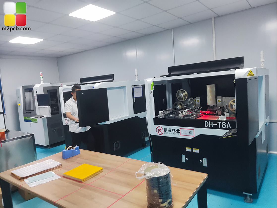
PI reinforcement is a documented step in the flexible circuit fabrication flow, used where a flex board needs local stiffness.
| Design input | Documented option | What it controls in the device |
|---|---|---|
| Base material | PI (polyimide) | Flexibility of the finished light board and its ability to follow a curved surface |
| Board thickness | 0.4 mm, 0.6 mm, 0.8 mm, 1.2 mm, 2.0 mm (board fabrication range) | Stiffness of the strip and how tightly it can be formed into the housing |
| Outer copper weight | 0.5 oz, 0.75 oz, 1 oz, 2 oz, 3 oz, 4 oz | Current carrying capacity and voltage drop along a long LED strip |
| Minimum line width | 0.05 mm | How much routing and how many LEDs fit per unit of board area |
| Minimum spacing | 3/3 mil | Manufacturing margin between conductors in dense LED layouts |
| Maximum width | 240 mm | Fit for wide light boards and panel formats |
| Length and supply format | 1 m or by reel | Continuous strip production versus discrete piece handling downstream |
| Layer count | 1 to 14 layer flexible PCB | Routing plus control circuitry inside one flexible body |
| Impedance control | Yes, on the 4-layer PCB build | Signal integrity for controlled-impedance lines |
| Test method | Flying Probe Test or Electrical test | Opens and shorts verification before assembly |
| Assembly options | Single or double sided, turnkey BOM, X-ray test, program burn | Whether the flex board becomes a finished PCBA |
Step-by-Step Breakdown: Turning a Design Brief Into a Quotable Flex Spec
Step 1: Write the device requirement before the board requirement
Start with what the finished product must do: total light length, how tightly it bends, whether it is worn against skin, where the connector sits, and how the board is fed into assembly. This step produces a short paragraph, not a drawing. Every later parameter should be traceable back to a sentence in it.
Step 2: Fix the substrate and the layer count
If the board must flex, the answer is PI. If the design also needs control circuitry on the same body, the layer count moves within the documented 1 to 14 layer flexible PCB range, and a 4-layer build brings impedance control into scope. If the project includes components, the PCBA path should be decided now, because single-sided or double-sided assembly, turnkey BOM handling, X-ray testing and program burning all affect the fabrication file package.
Step 3: Choose thickness by the mechanical job
Work from the documented set: 0.4 mm, 0.6 mm, 0.8 mm, 1.2 mm, 2.0 mm. Thin boards follow curves; thicker boards hold shape where the light board also has to stay flat. Where a connector or a mounting point needs local rigidity, PI reinforcement is the documented fabrication step used for that purpose, and it is easier to plan it at design stage than to add it later.
Step 4: Size outer copper to the current path, not to habit
Calculate what the strip carries over its full length, then select from the 0.5 oz to 4 oz outer copper range. Long LED strips and multi-LED therapy panels are the cases where this decision has visible consequences in the finished product.
Step 5: Set routing density deliberately
Use the 0.05 mm minimum line width and 3/3 mil minimum spacing only where the LED pitch demands it. Marking those areas explicitly on the drawing tells the factory where the tight tolerance matters and where it does not, which is exactly the information that keeps a quotation comparable between suppliers.
Step 6: Match width and supply format to the line
Check the design against the 240 mm maximum width. Then decide between 1 m sections and reel form. This is a production decision as much as a design decision: reel format is the format built for continuous strip production, while 1 m sections suit products assembled from discrete pieces. Choosing the format late is the most common reason a good flex design creates unnecessary handling cost.
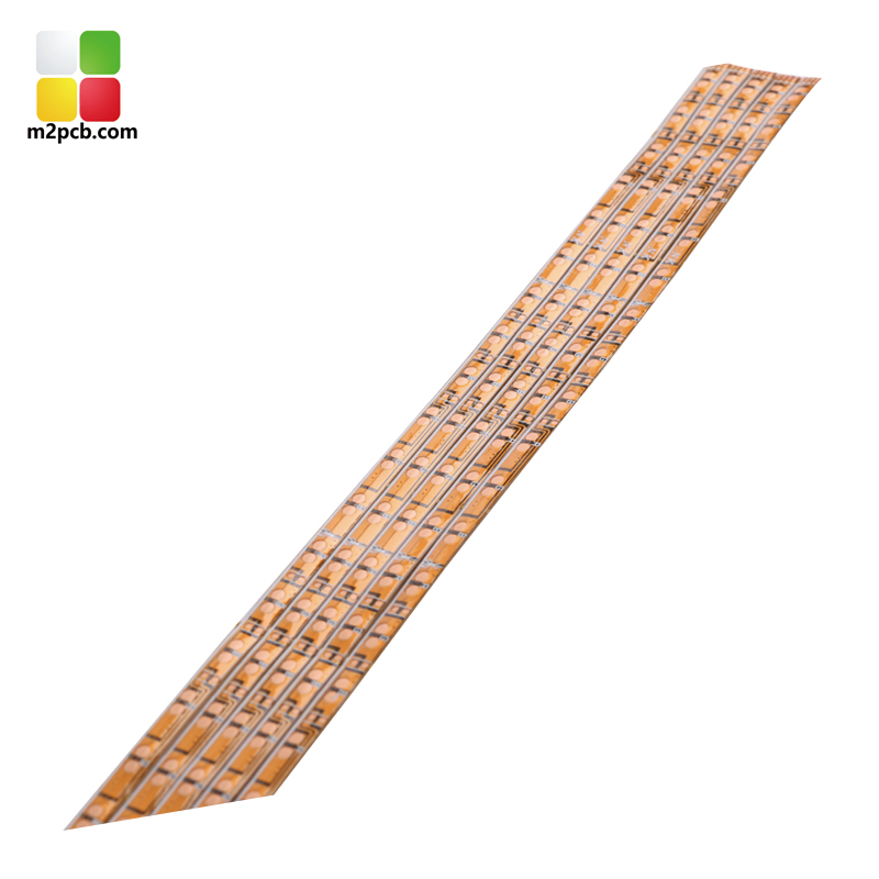
Flexible LED strip boards are documented as supplied in 1 m lengths or in reel form, which sets the handling path for downstream assembly.
Step 7: Define verification and compliance before the order
Write the test method into the specification: Flying Probe Test or Electrical test, backed by the documented 100% test, fly-probe, electronic testing and AOI flow, and by X-ray testing and program burning when assembly is included. In parallel, confirm the compliance scope. The UL certification held for the flexible LED PCB is number E530809, issued by Underwriters Laboratories Inc. for the North American market, and it applies to flexible circuit boards for medical aesthetics, automotive and electronic products under standards including UL6950-1, UL60065 and UL62368-1. IATF 16949:2016 certification number T184452, issued by NQA and valid from 2024-02-21 to 2027-02-21, applies to the automotive industry market. Where a project falls outside those stated scopes, that should be raised as an open question rather than assumed.
One-page flex spec checklist
- Device sentence: light length, bend requirement, contact surface, connector location.
- Substrate and layer count: PI, 1 to 14 layer range, impedance control if required.
- Thickness: one value from 0.4, 0.6, 0.8, 1.2 or 2.0 mm.
- Outer copper: one value or one range from 0.5 oz to 4 oz.
- Density: where 0.05 mm line width and 3/3 mil spacing are genuinely required.
- Size and format: within 240 mm width, supplied as 1 m or by reel.
- Verification: Flying Probe Test or Electrical test, plus assembly-level tests if applicable.
- Compliance: the market and product family the finished device must satisfy.
Use Cases: Three Device Families, Three Different Constraint Sets
LED lighting strips and soft light boards
Strip and soft light products put length and evenness first. The binding constraints are usually the 1 m or reel supply format, the 240 mm maximum width, and the copper weight that keeps brightness consistent from one end of the strip to the other. Because strip products are produced continuously, reel format is the natural fit when the downstream line is built for it, and the same 0.05 mm line width and 3/3 mil spacing that allow dense LED placement also set the fabrication difficulty of the whole order.
Medical aesthetic devices
Aesthetic devices work in the opposite direction: short lengths, tight geometry, high LED density in a small treatment head. Documented examples from the M2PCB product portfolio include a beauty eye device lamp board, a Meiya lamp PCBA and an aesthetic atomization PCBA. Here the 0.05 mm minimum line width and 3/3 mil minimum spacing matter more than total length, and compliance matters more than format, because the UL certification scope held for flexible LED boards explicitly includes medical aesthetics. Confirming that a specific device falls inside that scope is a buyer action, not an assumption.
Physiotherapy and red light therapy products
Physiotherapy products combine the two profiles. A belt has to be long enough to wrap, flexible enough to conform, and mechanically stable enough to survive repeated use. The documented therapy lamp PCB and red light therapy belt circuit boards sit exactly in this category, and one documented case shows the scale this segment can reach: a red light therapy products ODM in the United States ordered 500,000 pieces for a waist pain relief belt over a two-year period, with the case record describing outcomes such as improved blood circulation, pain relief through photobiomodulation, and support for abdominal therapy modes, together with the non-invasive, painless and safe character that made the product suitable for rehabilitation, sports medicine and home care use.
Comparison: What the Evidence Supports for Each Device Family
The comparison below maps each device family to the documented material and the documented product evidence, so that a specification discussion can start from artefacts rather than adjectives.
| Device family | Substrate | Documented product evidence | Documented verification |
|---|---|---|---|
| LED lighting strips and soft light boards | PI (polyimide) | Flexible circuit board, LED strip light, flexible soft light board; supply as 1 m or by reel | Flying Probe Test or Electrical test |
| Medical aesthetic devices | PI (polyimide) | Beauty eye device lamp board, Meiya lamp PCBA, aesthetic atomization PCBA; UL scope includes medical aesthetics | Flying Probe Test or Electrical test; X-ray test and program burn at PCBA level |
| Physiotherapy and red light therapy products | PI (polyimide) | Therapy lamp PCB, red light therapy belt circuit board, red light therapy soft light circuit board; 500,000 piece cosmetic-grade belt case over 2 years | Flying Probe Test or Electrical test |
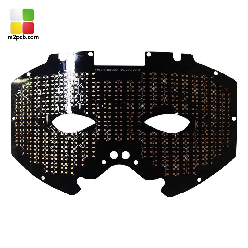
A beauty eye device lamp board, representative of the dense, short-format flexible builds used in medical aesthetic equipment.
Frequently Asked Questions
Which certifications apply to a flexible LED PCB for aesthetic or therapy devices, and what do they actually cover?
The documented certification for the flexible LED PCB is UL certification number E530809, issued by Underwriters Laboratories Inc. (UL) and valid for the North American market. Its stated scope is flexible circuit boards for medical aesthetics, automotive and electronic products, and the standards referenced are UL6950-1, UL60065 and UL62368-1. The same product is also covered by IATF 16949:2016 certification number T184452, issued by NQA and valid from 2024-02-21 to 2027-02-21, which applies to the automotive industry market. At the standards level, UL 796F addresses flammability, MOT and CTI specifically for flexible substrates, and IPC-6013 is the performance specification for flexible printed wiring. Because UL scope is written around defined product families, a buyer should confirm that a specific device falls inside the stated scope rather than treat certification as automatically transferable.
Can the physical specification be customized for a specific light board design?
Yes. The documented customization basis is production to the customer's request under an OEM or ODM model. Within the flexible LED PCB specification, the adjustable parameters include board thickness options of 0.4 mm, 0.6 mm, 0.8 mm, 1.2 mm and 2.0 mm, outer copper weights of 0.5 oz, 0.75 oz, 1 oz, 2 oz, 3 oz and 4 oz, a minimum line width of 0.05 mm, minimum spacing of 3/3 mil, a maximum width of 240 mm, and supply as 1 m lengths or in reel form, on a polyimide base. Layer counts run from 1 to 14 layer flexible PCB, impedance control is available on the 4-layer build, and assembly can be single sided or double sided with turnkey BOM parts, X-ray testing and program burning.
What drives the cost of a flexible LED PCB and its assembly?
Cost in a flex project follows the parameters that consume process difficulty and board area: the copper weight selected from the 0.5 oz to 4 oz range, the layer count up to 14 layers, the total board area of a long strip or a wide light panel up to 240 mm, and how much of the layout actually uses the 0.05 mm minimum line width and 3/3 mil minimum spacing. Thickness selection, PI reinforcement steps, the required test method, and the chosen supply format of 1 m sections versus reel all influence the quotation as well. When assembly is included, single-sided or double-sided assembly, turnkey BOM sourcing, X-ray testing and program burning become additional cost lines. Rather than estimate a price band from a catalogue, the practical approach is to send the one-page spec described above and request a quotation against it, since MOQ for a prototype is documented as 1 unit.
How should a new flex light board be validated before mass production?
Validation starts with a prototype order rather than a full production run, and the documented minimum order quantity of 1 unit makes that practical. The prototype should be specified with the same parameters intended for production: PI substrate, the chosen thickness and outer copper weight, the same line width and spacing constraints, the same width and supply format. Verification on the fabricated board is performed by Flying Probe Test or Electrical test, within a quality flow that includes 100% test, fly-probe, electronic testing and AOI test. If the board also carries components, the PCBA stage adds X-ray testing and program burning. The sample stage is also the point to validate the mechanical fit, since flexibility behaviour is difficult to assess from a drawing alone.
What is the documented lead time, and how do long strips and reel formats affect downstream assembly?
Documented lead time is 3 to 20 days, with monthly capacity of 40,000 square metres. The supply format decision is what connects the flex board to the assembly line. Boards supplied as 1 m sections are handled as discrete pieces and suit products assembled from fixed-length parts, while reel form is designed for continuous strip production and for assembly equipment that feeds from a reel. Choosing the format changes fixturing, handling and the risk of damage to a long flexible strip, so it should be settled together with the assembly partner before fabrication begins rather than after the boards arrive. If you want to work through that decision on a real design, M2PCB accepts briefs and flex drawings through www.m2pcb.com or by email at pcb@dreamlandpcb.com, and the practical next step is to send the one-page spec with a sample request or quotation request attached.
Conclusion: The Matching Exercise in One Page
Matching a flexible PCB spec to a lighting, medical aesthetic or physiotherapy product comes down to a small number of decisions made in the right order. Start from the device: how long the light has to be, how tightly it bends, whether it is worn against skin, and how it will be handled downstream. Then fix the substrate as polyimide, select a thickness from the documented 0.4 mm to 2.0 mm range, size outer copper between 0.5 oz and 4 oz to the current the strip actually carries, reserve the 0.05 mm line width and 3/3 mil spacing for the areas that truly need density, stay within the 240 mm maximum width, and choose between 1 m sections and reel form with the assembly line in view. Specify verification as Flying Probe Test or Electrical test, and confirm compliance scope early rather than at the end.
That sequence produces a specification a factory can quote from and a device team can defend. It is also the sequence that keeps a therapy lamp, an LED strip and an aesthetic treatment head from sharing the same generic board parameters when they need very different ones.
Next step: turn your brief into a quotable flex spec
Send M2PCB the device description and the one-page parameter list from this guide, and the team will come back with a build recommendation, a sample plan starting from a 1 unit minimum, and a production lead time of 3 to 20 days. Website: www.m2pcb.com | Email: pcb@dreamlandpcb.com | WhatsApp: +86 136-2262-8609
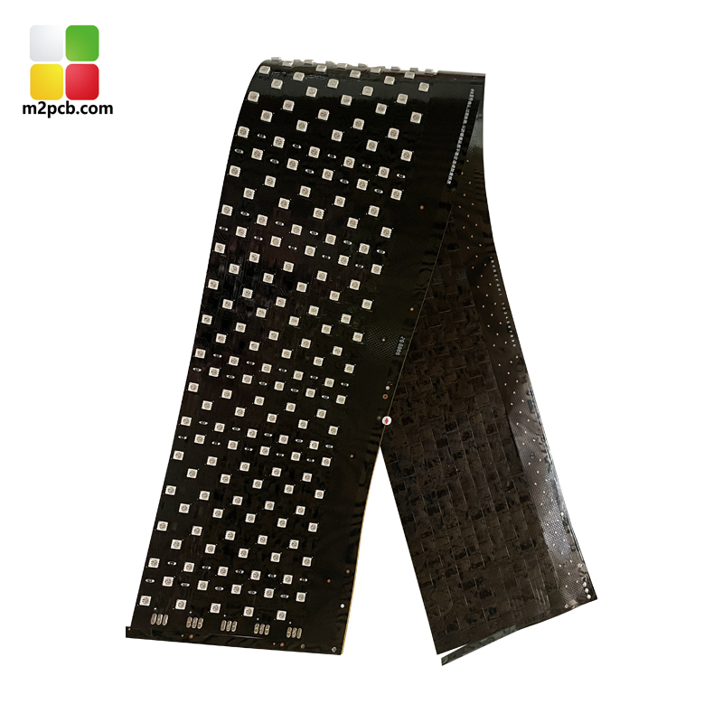
Red light therapy belt circuit boards are one of the documented physiotherapy builds produced on flexible polyimide substrates.
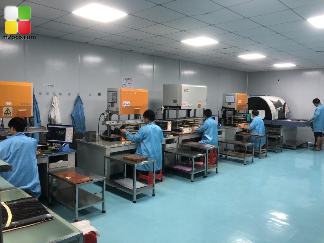
Electrical testing is the final gate before a flexible board is released to assembly.
¿Tiene preguntas o necesita más detalles?
Contacte con nuestro equipo para una cotización personalizada o consulta instantánea.
Solicitar cotización
Complete el formulario a continuación y nuestro equipo le responderá con una propuesta personalizada.
Chat directo de WhatsApp
¿Prefiere chatear en tiempo real? Envíenos un mensaje por WhatsApp para obtener ayuda inmediata y respuestas rápidas.
- Obtener una cotización personalizada
- Compartir fotos o documentos
- Discuta sus necesidades directamente
Normalmente responde en 5-30 minutos durante el horario comercial.