 8000m²
 200

FR4 vs PI vs IMS: A Buyer's Comparison Guide for Flexible LED PCB Substrates
Three substrate families cover most flexible LED PCB and PCBA programs: FR4, polyimide (PI) and IMS. The useful comparison is not which material is best in general, but which one matches the mechanical envelope, the thermal load and the compliance file of a specific LED product. Framed that way, the substrate decision becomes something you can document, quote and prototype instead of an argument between suppliers.
This guide is written for buyers in the research stage. It compares the three materials using published product data from the M2PCB Flexible LED PCB, the FR4 PCB board range supplied in TG130–TG170 grades, and PCBA programs that accept FR4, PI and IMS as base materials.
Why the Substrate Decision Comes First
In LED products, the term “LED PCB” is used for at least three different objects, and that is where most substrate confusion begins.
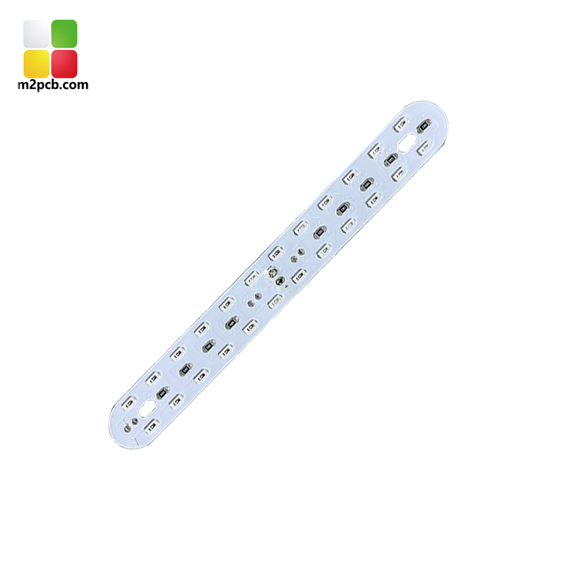
A flexible printed circuit is a circuit built on a thin, pliable dielectric film rather than a rigid laminate. M2PCB’s Flexible LED PCB is a flexible LED circuit board, also described as an LED flexible light strip, with a maximum width of 240 mm, a minimum line width of 0.05 mm and a minimum spacing of 3/3 mil. It is supplied in 1 m lengths or by reel and tested by flying probe test or electrical test.
A PCB board is the bare circuit board before components are mounted. M2PCB’s board product is a 4-layer, FR4-based design offered in TG130, TG140, TG150 and TG170 grades, in thicknesses of 0.4 mm, 0.6 mm, 0.8 mm, 1.2 mm and 2.0 mm, with outer copper weights from 0.5 oz to 4 oz and impedance control.
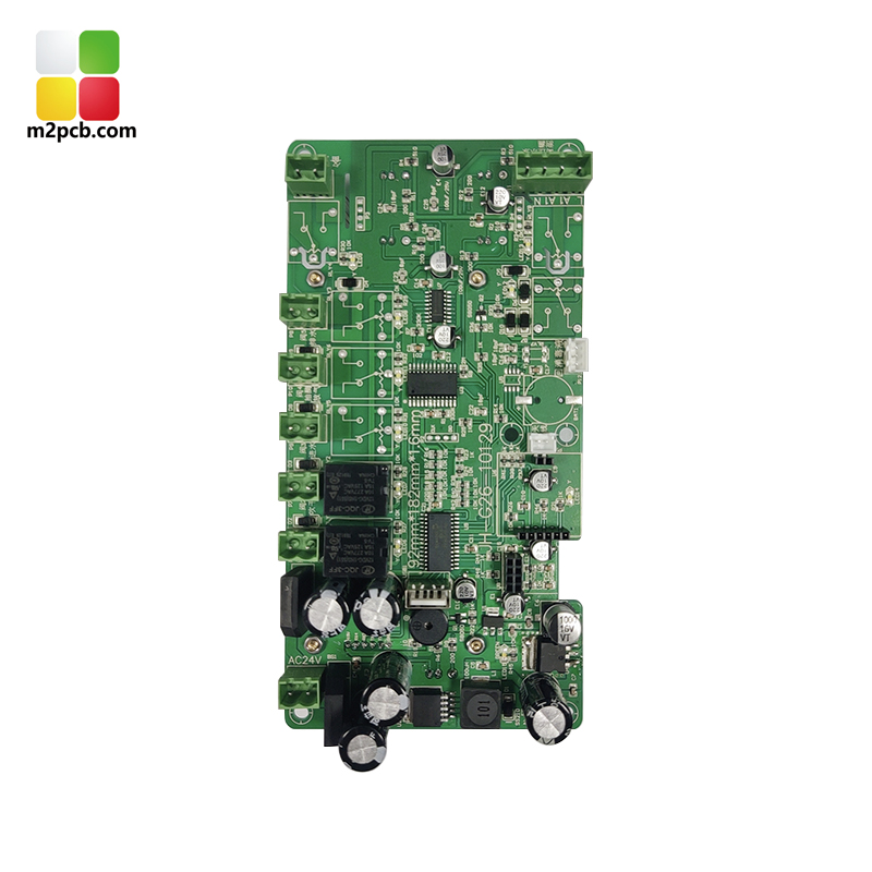
A PCBA is a printed circuit board assembly: the finished, populated board. M2PCB assembles on one side or both sides, offers turnkey BOM sourcing, and applies X-ray testing and program burning to the finished assembly.
Once those objects are separated, the material question reduces to three requirements that pull in different directions: how flat the board must stay, how much heat has to leave the LEDs, and what the product’s compliance file will accept. FR4, PI and IMS are three different answers to that same set of questions.
Industry Background: A Fast-Moving Segment Inside a Large PCB Industry
The global flexible printed circuit board market was estimated at USD 23.89 billion in 2024 and is projected to reach USD 50.90 billion by 2030, a compound annual growth rate of 13.7%, according to Grand View Research. The same dataset puts Asia-Pacific at 76.8% of 2024 flexible PCB revenue, reflecting the concentration of electronics manufacturing in that region.
The size of that regional base shows up in China’s wider PCB industry, where revenue was expected to reach USD 120.8 billion in 2024 with exports accounting for approximately 16.5% of total revenue, per IBISWorld. Inside the flexible segment, mobile phone applications remained the largest single application at 55.8% of global market value in 2024, according to TPCA and ITRI data published via I-Connect007. The same dataset ranks the largest flexible PCB manufacturers by 2024 share: Zhen Ding Technology at 19.9%, Dongshan Precision at 14.6% and Nippon Mektron at 13.0%.
Market sizing for this segment should be read with care. Published 2024 estimates range from USD 18.87 billion (TPCA/ITRI) to USD 21.5 billion (BCC Research) to USD 23.89 billion (Grand View Research), depending on how the flexible segment is scoped. The growth direction is consistent across sources even when the absolute figure is not.
Two standards frame the compliance side of substrate selection. UL 796F addresses safety requirements specific to flexible printed circuits, including flammability (V-rating), MOT and CTI for flexible substrates. IPC-6013 is the globally recognized performance specification for flexible printed wiring, detailing reliability requirements under different environmental conditions. A substrate decision made without reference to those two documents tends to create rework at the qualification stage.
How FR4, PI and IMS Behave in an LED Build
The three families differ at three points in a build: how the board behaves mechanically, how heat leaves the LED area, and how the board is processed and assembled.
Polyimide (PI): the material that bends
Polyimide is a polymer film, and it is the base material behind M2PCB’s Flexible LED PCB. Because the circuit is built on a thin film rather than a rigid laminate, the board can follow a curved housing, fold into a compact lamp head or run the length of a light strip. That mechanical freedom is why the polyimide-based flexible LED board is published for lighting, medical aesthetic and physiotherapy products, where lamp boards have to sit close to a body or wrap around a device.
The published parameters of the flexible LED board are: material PI; length 1 m or by reel; maximum width 240 mm; minimum line width 0.05 mm; minimum spacing 3/3 mil; flying probe test or electrical test.
What polyimide does not do is act as a heat spreader. Heat moves mainly through the copper on the film, and a thin film offers limited spreading area, so high-output LED arrays on PI generally rely on the housing, a metal core or a dedicated heat sink to move heat away from the LEDs. The design consequence is practical: spread the emitters over a wider area or plan a thermal path behind the film.
FR4: the rigid laminate that carries control and power sections
FR4 is a glass-reinforced epoxy laminate. It holds a fixed shape, which makes it a natural home for the electronics that feed the light: driver boards, control boards and power sections. M2PCB’s FR4 board is a 4-layer product offered in TG130, TG140, TG150 and TG170 grades, with thickness options of 0.4 mm, 0.6 mm, 0.8 mm, 1.2 mm and 2.0 mm, outer copper from 0.5 oz to 4 oz, impedance control and flying probe testing.
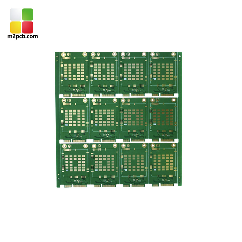
Published application fit for the FR4 board product covers consumer electronics, industrial control, automotive, communication, medical and lighting. The same rigid board family is listed in M2PCB’s application scenario data for automotive electronics, industrial control and medical work, alongside PCB fabrication, SMT processing and through-hole assembly.
IMS: the metal-backed substrate
IMS stands for insulated metal substrate. A dielectric layer is bonded to a metal base so that the base itself becomes part of the thermal path, while the board stays rigid in the same way as a metal-backed panel. M2PCB lists IMS alongside FR4 and polyimide as a base material for its PCBA programs, which are published for artificial intelligence, new energy, medical electronics, aerospace and military industries.
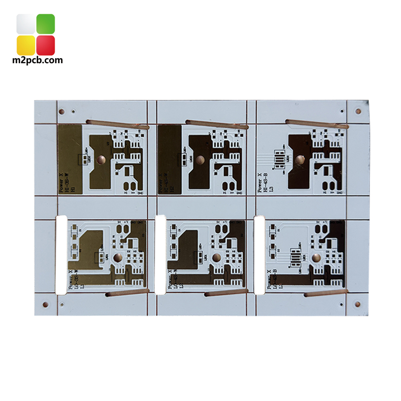
One limit is worth stating plainly. M2PCB’s published product data names IMS at the material level for assembly programs, rather than publishing a fixed substrate table for it. Layer stack, copper weight, board outline and assembly side are therefore confirmed against the actual design files, because these products are built to customer specification. Buyers should expect IMS parameters to be defined during quotation rather than read from a catalogue page.
M2PCB’s Three Product Lines Mapped to the Three Materials
The practical value of this mapping is knowing which line a project belongs to before requesting a quotation.
- Flexible LED PCB (PI) — flexible LED circuit boards and LED flexible light strips, supplied in 1 m lengths or by reel, up to 240 mm wide, with a minimum line width of 0.05 mm and minimum spacing of 3/3 mil, verified by flying probe test or electrical test. Published for lighting, medical aesthetic and physiotherapy products.
- PCB board (FR4) — 4-layer FR4 boards in TG130, TG140, TG150 and TG170 grades, 0.4–2.0 mm thickness, 0.5–4 oz outer copper, impedance control and flying probe testing. Published for consumer electronics, industrial control, automotive, communication, medical and lighting.
- PCBA (FR4, PI, IMS) — single- or double-sided assembly, turnkey BOM sourcing, X-ray testing and program burning. Published for artificial intelligence, new energy, medical electronics, aerospace and military industries.
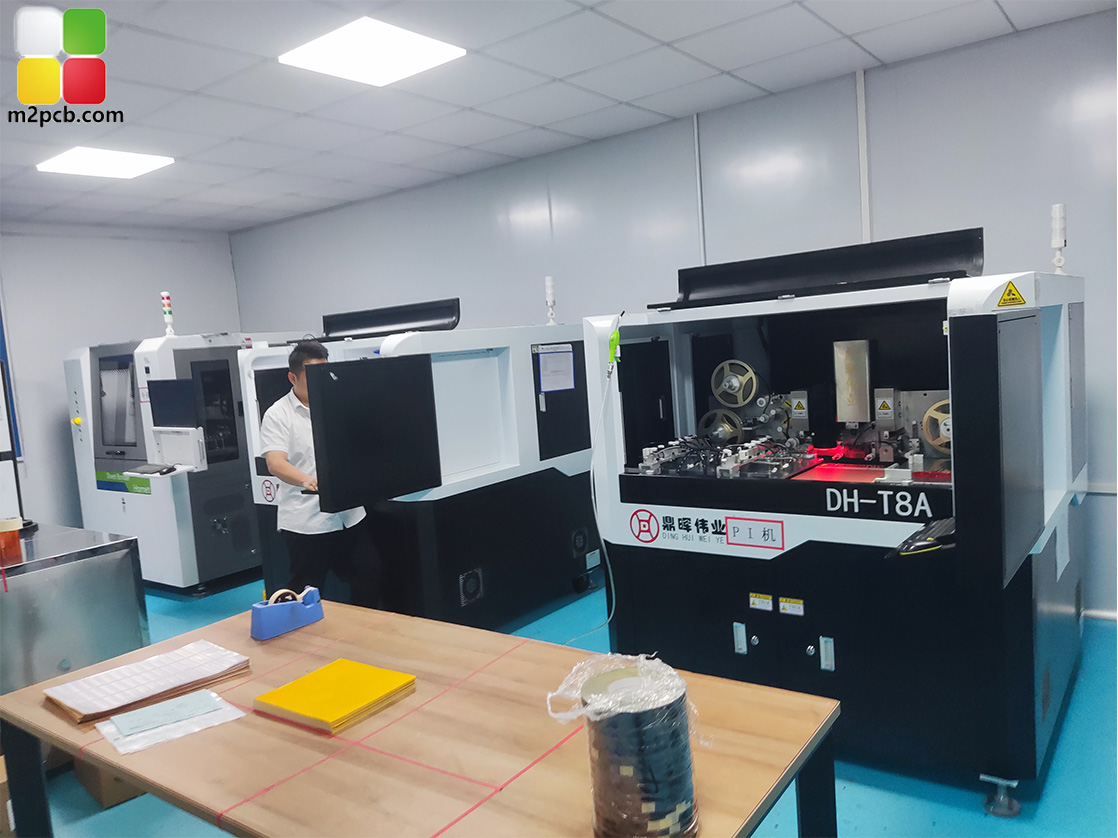
The supplier context behind those lines is verifiable: M2PCB was established in 2000 and operates an 8,000 m² manufacturing facility with approximately 200 employees and a 30-engineer R&D team, while the technical and management team carries more than 10 years of industry experience. Production covers 1 to 14 layer flexible PCBs and PCB assembly, with monthly delivery of 800 product varieties, a monthly production area of 100,000 m² and annual output of 360,000 m². Quality is controlled under an ISO quality system, and many of the materials used have UL and RoHS approval. Exports account for approximately 70% of sales, with main markets in Europe, North America, South America and Australia.
Step-by-Step: How to Choose Between FR4, PI and IMS
- Define the mechanical envelope. If the board must bend, fold, follow a curve or survive movement, polyimide is the family to evaluate. If the board is fixed and only has to fit a plane, FR4 or IMS is the usual starting point.
- Define the thermal load. If the LEDs are the dominant heat source and the substrate itself has to help move that heat, evaluate IMS. If heat can leave through the housing or a metal core, polyimide remains viable. If the thermal load sits with the driver electronics on a rigid section, FR4 is normally adequate.
- Match the application to published fit. Compare your product against the published application lists: PI for lighting, medical aesthetic and physiotherapy; FR4 for consumer electronics, industrial control, automotive, communication, medical and lighting; PCBA on FR4, PI or IMS for artificial intelligence, new energy, medical electronics, aerospace and military industries.
- Confirm the compliance path. Check UL 796F and IPC-6013 obligations first, then confirm material-level UL and RoHS approvals for the exact stack-up you intend to release.
- Release the right files. PCB manufacturing requires circuit files such as PCB data, Gerber, PCB or PCBDoc, while SMT processing requires a BOM list giving component model, package size and quantity.
- Build the prototype. PCB fabrication converts the designed circuit into a physical board through copper cladding, etching, drilling and plating. SMT assembly then places components with automatic pick-and-place machines after solder paste printing and reflow soldering. Through-hole assembly covers components that cannot be placed automatically, including insertion, wave soldering, lead cutting, post-soldering processing and board cleaning.
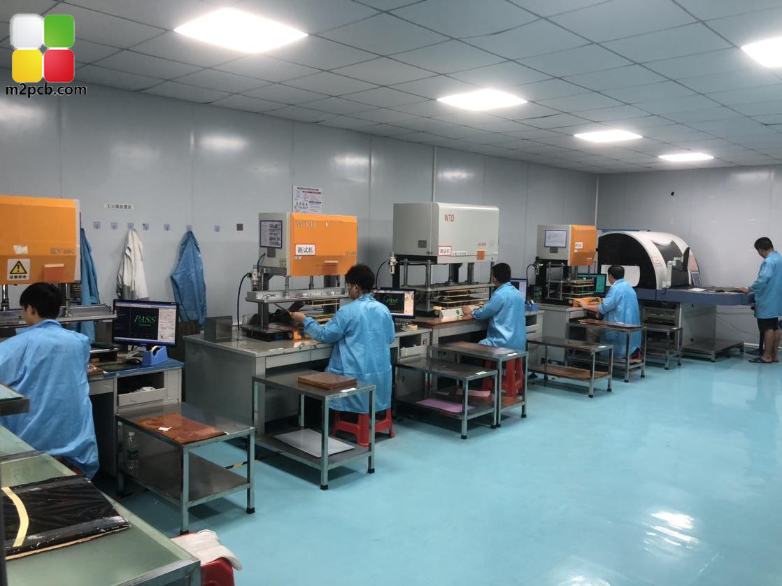
- Validate before scaling. Bare boards are checked by flying probe test or electrical test; assemblies are checked with X-ray testing, program burning and visual inspection. A board that passes electrical test but fails in the housing has a mechanical or thermal problem rather than an electrical one, so validate inside the real enclosure.
Use Cases: Where Each Substrate Fits
Polyimide in lighting and body-contact devices
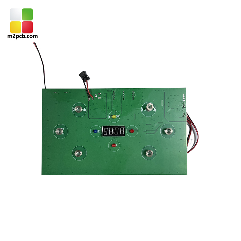
The published application fit for the polyimide-based Flexible LED PCB is lighting, medical aesthetic and physiotherapy products. In practice this covers LED flexible light strips, soft light boards, red light therapy boards, therapy lamp boards and beauty device lamp boards, where the light source has to follow a contoured surface. The 240 mm maximum width and 0.05 mm minimum line width define what can be routed on such a board, while the 3/3 mil minimum spacing sets how densely the emitters can be laid out.
FR4 in control and driver sections
FR4 carries the electronics that feed the light: driver boards, control boards and power sections in consumer electronics, industrial control, automotive, communication, medical and lighting products. A 4-layer stack with impedance control gives the designer a defined environment for controlled-impedance nets, with thickness from 0.4 mm to 2.0 mm and outer copper up to 4 oz for higher-current traces.
PCBA on FR4, PI or IMS in system-level products
Once the board is populated, the material question moves to the assembly program. M2PCB’s PCBA line accepts FR4, PI and IMS and is published for artificial intelligence, new energy, medical electronics, aerospace and military industries. Single- or double-sided assembly, turnkey BOM sourcing, X-ray testing and program burning are all part of the published capability set, which matters when a flexible LED board and its controller are delivered as one tested assembly instead of two separate parts.
Side-by-Side Comparison
| Dimension | FR4 | Polyimide (PI) | IMS |
|---|---|---|---|
| Material nature | Glass-reinforced epoxy laminate, rigid | Polymer film, flexible | Dielectric bonded to a metal base |
| Shape behaviour | Holds a fixed shape | Bends and folds; follows curved housings | Rigid, with a fixed outline |
| Heat path | Through copper features and vias into the laminate and out to the enclosure | Along thin copper traces; spreading is limited by the thin film | Metal base acts as a heat spreader beneath the circuit |
| M2PCB published data | 4-layer board, TG130/TG140/TG150/TG170, 0.4–2.0 mm thickness, 0.5–4 oz outer copper, impedance control, flying probe test | Flexible LED PCB, max width 240 mm, 1 m or by reel, min line width 0.05 mm, min spacing 3/3 mil, flying probe or electrical test | Named as a PCBA base material alongside FR4 and PI |
| Published application fit | Consumer electronics, industrial control, automotive, communication, medical, lighting | Lighting, medical aesthetic, physiotherapy products | PCBA programs published for artificial intelligence, new energy, medical electronics, aerospace and military industries |
| Typical role in an LED product | Driver, control and power section | Light-emitting surface, strip and soft light boards | Boards where the substrate is part of the thermal design |
FR4 and PI parameters in this table come from M2PCB’s published product data. IMS is published at the material level for PCBA programs and is defined per project. Standards referenced: UL 796F and IPC-6013.
FAQ
Which standards govern a flexible LED PCB substrate, and how do I verify compliance?
UL 796F covers safety requirements specific to flexible substrates, including flammability (V-rating), MOT and CTI, while IPC-6013 is the recognized performance specification for flexible printed wiring and its reliability requirements under different environmental conditions. M2PCB operates an ISO quality system, and many of the materials used in its Flexible LED PCB and PCBA production have UL and RoHS approval. Because approvals apply to specific materials rather than to a supplier in general, confirm that the certificate matches the exact stack-up you plan to release.
Can one supplier deliver both the flexible LED board and the assembled PCBA?
M2PCB manufactures 1 to 14 layer flexible PCBs and provides PCB assembly from the same operation. The Flexible LED PCB is built on PI; the FR4 board range covers 4-layer designs in TG130, TG140, TG150 and TG170 grades; and PCBA programs accept FR4, PI and IMS with single- or double-sided assembly, turnkey BOM sourcing, X-ray testing and program burning. The company runs an 8,000 m² facility with approximately 200 employees, a 30-engineer R&D team, monthly delivery of 800 product varieties and a monthly production area of 100,000 m².
What drives the cost of an FR4, PI or IMS board?
Quotations are built from the parameters a buyer specifies: material family, layer count (flexible boards range from 1 to 14 layers), board thickness (0.4–2.0 mm on the FR4 board range), outer copper weight from 0.5 oz to 4 oz, assembly on one or both sides, BOM completeness for turnkey sourcing, and the test method. Because M2PCB builds to customer specification, the price follows the released stack-up and BOM rather than a catalogue part number. Freeze the material family before requesting comparable quotes, otherwise the offers describe different products.
Can I validate a substrate choice with a prototype before committing to production?
Yes. PCB fabrication requires circuit files such as PCB data, Gerber, PCB or PCBDoc, and SMT assembly additionally requires a BOM list giving component model, package size and quantity. Prototypes are checked with flying probe test or electrical test on the bare board, and with X-ray testing, program burning and visual inspection after assembly. A prototype that passes electrical test should also be validated in its final housing, because bending behaviour and heat spreading are decided by the mechanical design around the board, not only by the board itself.
What affects scheduling, and how do I start a substrate evaluation?
Scheduling depends largely on how much of the chain stays in one place. M2PCB covers PCB fabrication (copper cladding, etching, drilling, plating), SMT assembly (solder paste printing, pick-and-place, reflow soldering) and through-hole assembly (insertion, wave soldering, lead cutting, post-soldering processing, board cleaning) in-house, and delivers 800 product varieties per month from a monthly production area of 100,000 m². To start, send Gerber or PCB data for fabrication and a BOM for assembly to pcb@dreamlandpcb.com, call or message +86 136-2262-8609, or request a sample and quotation through www.m2pcb.com.
Conclusion
The FR4 versus PI versus IMS decision is settled by three inputs: the mechanical envelope, the thermal load and the compliance requirement. Polyimide is the film-based family for boards that must bend, published for lighting, medical aesthetic and physiotherapy products. FR4 is the rigid laminate used for 4-layer boards in TG130–TG170 grades, with thickness from 0.4 mm to 2.0 mm and outer copper from 0.5 oz to 4 oz, published for consumer electronics, industrial control, automotive, communication, medical and lighting. IMS is the metal-backed option named in M2PCB’s PCBA material set alongside FR4 and PI, with its parameters confirmed per project.
Buyers who freeze the material family first get quotations that describe the same product, and can move into prototyping with files that match the process: Gerber or PCB data for fabrication, a BOM for assembly.
Next Step: Sample, Prototype and Quotation
M2PCB builds flexible LED PCBs on polyimide and assembles PCBA on FR4, PI and IMS. Send your Gerber or PCB data and BOM for a technical review, request a prototype run, or ask for a sample and quotation.
Email: pcb@dreamlandpcb.com | Tel / WhatsApp: +86 136-2262-8609 | Website: www.m2pcb.com
¿Tiene preguntas o necesita más detalles?
Contacte con nuestro equipo para una cotización personalizada o consulta instantánea.
Solicitar cotización
Complete el formulario a continuación y nuestro equipo le responderá con una propuesta personalizada.
Chat directo de WhatsApp
¿Prefiere chatear en tiempo real? Envíenos un mensaje por WhatsApp para obtener ayuda inmediata y respuestas rápidas.
- Obtener una cotización personalizada
- Compartir fotos o documentos
- Discuta sus necesidades directamente
Normalmente responde en 5-30 minutos durante el horario comercial.