
Wire-to-Board Connectors: A PCB Connector Discovery Guide

A wire-to-board connector is a board-level interconnect that terminates a discrete wire or cable harness onto a printed circuit board. It normally consists of a PCB-mounted header or wafer plus a cable-side housing or termination, and it carries power, signal, or both between the board and the wiring that leaves it. Together with board-to-board (B2B) and wire-to-wire (W2W) connectors, it forms one of the three basic interconnect architectures used at PCB level.
The category matters commercially as well as technically. Market research published by Market Research Future estimates the global PCB connector market at USD 33.83 billion in 2025, with a projected value of USD 47.96 billion by 2035. Within that market, Global Market Insights reports that board-to-board connectors were the largest product type in 2025, accounting for approximately 24.3% revenue share and USD 4,459.8 million in revenue. Wire-to-board connectors occupy the adjacent space, where a cable harness has to reach the board rather than two boards meeting each other.
For buyers and design engineers working at the awareness and research stage, the practical difficulty is rarely understanding what a wire-to-board connector is. The difficulty is deciding which sub-architecture fits a given design — and being able to recognise the same concept when suppliers describe it with different names. This guide maps the category, the architectures inside it, the specification parameters that actually drive selection, and the trade-offs that are often left out of product pages.
What a Wire-to-Board Connector Is — and What It Is Not
The cleanest way to distinguish the three board-level architectures is by asking what is being joined at each end of the connection.
| Architecture | What It Connects | Typical Selection Drivers |
|---|---|---|
| Board-to-Board | Two PCBs, usually stacked or mezzanine-mounted | Stacking height, pitch, alignment tolerance, data rate, current per pin |
| Wire-to-Board | A cable or discrete wire into a PCB | Pitch, current rating, wire gauge, locking, assembly method, environment |
| Wire-to-Wire | Two cable ends, with no board at the interface | Sealing, current capacity, vibration resistance, cable exit angle |
The distinction matters because the same physical product family is sometimes marketed under more than one label. A wafer connector with a crimp housing is a wire-to-board part; the same housing mated to another cable-end housing is a wire-to-wire part. When a buyer searches for a “PCB connector,” the results will span all three architectures, plus board-termination components such as press-fit terminals that do not involve a cable at all.
The Discovery Problem: Terminology Before Specification
Most early-stage wire-to-board evaluation starts with a component list that names a function rather than a part. Terms such as pin header, female header, box header, wafer, FPC/FFC, IDC and RAST describe different families, different termination methods, and in some cases different industry conventions. The result is a discovery phase in which buyers compare products that are not actually alternatives to each other.
A more reliable sequence is to fix four architectural questions before comparing any part numbers:
- What terminates at the cable side — a crimped discrete wire, a flat flexible cable, or a mass-terminated ribbon or RAST-style connection?
- How many positions are required, and does the design need power contacts, signal contacts, or a mixed layout?
- What is the operating environment — indoor control electronics, an engine bay, a sterilisation cycle, or an outdoor enclosure?
- How is the connector assembled — hand mating, automated SMT placement, or a solderless press-fit process?
Only after those questions are answered does pitch, current rating and plating become meaningful comparison criteria. This is also the point at which a supplier conversation becomes productive, because the supplier can be asked for a specific family rather than for a general catalogue.
Wire-to-Board Architectures in Practice
1. Crimp-to-wafer connectors
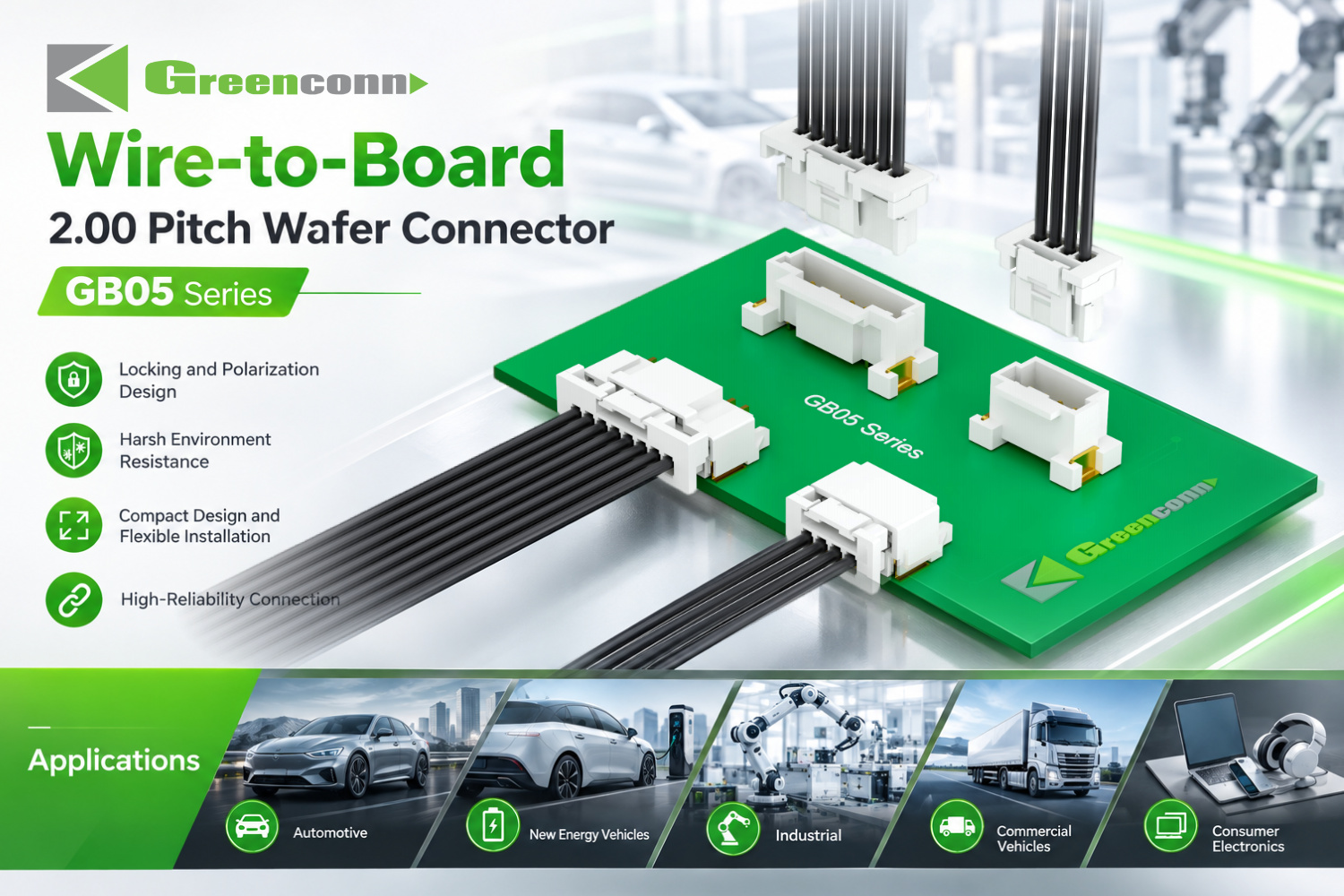
The most familiar wire-to-board arrangement uses a PCB-mounted wafer and a cable-side housing that accepts crimped terminals. Greenconn’s GB01 series is a 1.25 mm pitch wafer connector rated at 1 A AC/DC and 50 V AC/DC, with contact resistance of 30 mΩ maximum, insulation resistance of 100 MΩ minimum, dielectric withstanding voltage of 500 V AC per minute, and an operating range of −25 °C to +85 °C, using phosphor bronze contacts and a PA 9T insulator. The GB05 series moves to a 2.00 mm pitch with a 3.00 A AC/DC rating, 125 V AC/DC, contact resistance of 25 mΩ maximum, 1000 V AC per minute dielectric withstanding voltage and a wider −40 °C to +125 °C operating range, with a locking and polarisation design.
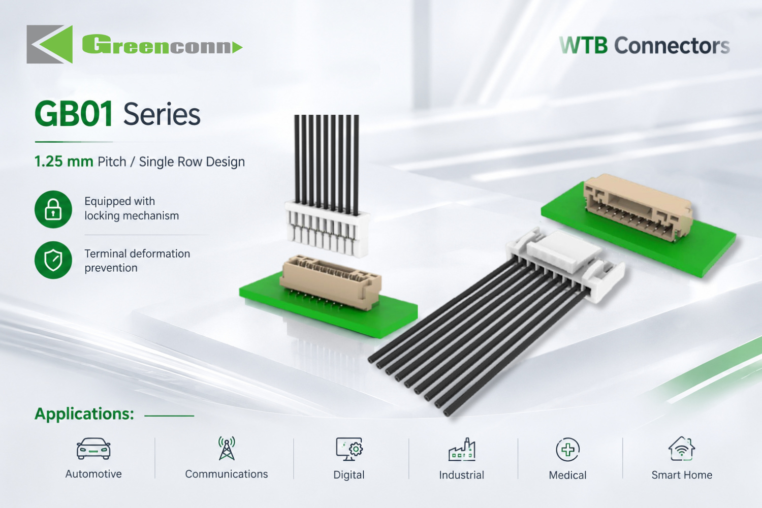
The practical difference between the two examples is not simply “smaller versus larger.” A 1.25 mm pitch part typically trades current capacity and thermal headroom for board-space reduction, while a 2.00 mm pitch part with a locking structure is usually chosen where vibration or cable pull-through is a real risk. Choosing the finer pitch first and discovering a current problem later is a common and avoidable design loop.
2. FPC/FFC connectors
Where the cable is a flat flexible cable rather than a discrete wire, the connector architecture changes entirely. Greenconn’s CFAD102 is a 0.50 mm pitch FPC/FFC wire-to-board connector rated at 0.50 A and 50 V AC/DC, with contact resistance of 30 mΩ maximum, insulation resistance of 500 MΩ minimum, dielectric withstanding voltage of 500 V and an operating temperature of −25 °C to +85 °C, using phosphor bronze contacts and an LCP or nylon insulator.
The boundary worth stating explicitly: at 0.50 mm pitch and a 0.50 A rating, an FPC/FFC connector is a signal and low-power interconnect. It is not a substitute for a power connector, and a design that attempts to route motor or heater current through a fine-pitch flex interface is using the part outside its stated envelope.
3. Insulation displacement and RAST-style direct connection
RAST connectors are a wire-to-board family widely used in appliance and control-board wiring. Greenconn’s CSGA106 is a RAST 2.5 connector with a 2.50 mm pitch and 2 to 15 pins, rated at 4 A per pin at an ambient of 60 °C and 2 A per pin at 100 °C, 32 V AC/DC, contact resistance of 10 mΩ, insulation resistance of 1000 MΩ, dielectric withstanding voltage of 500 V AC for one minute and an operating range of −40 °C to +130 °C, for AWG22 to AWG24 wire. The CSGA110 is a RAST 5.0 version with a 5.00 mm pitch, 2 to 9 pins, the same 4 A per pin at 60 °C and 2 A per pin at 100 °C ratings, 1200 V AC dielectric withstanding voltage and a −40 °C to +125 °C range.
Two characteristics define this family. First, insulation displacement (IDC) piercing removes the wire-stripping step, which reduces handling time and the variability that comes with manual preparation. Second, colour coding and keying allow visual identification on an assembly line, which matters when several similar harnesses terminate on the same control board. The trade-off is that IDC termination is intended for specific wire gauges — AWG22 to AWG24 in these examples — and using an out-of-range wire compromises the connection.
4. Solderless press-fit board termination
Press-fit is not a wire-to-board connector in the strict sense, because no cable is involved at the interface; the compliant pin is pressed directly into a plated-through hole. It is included here because it is frequently considered alongside wire-to-board parts as an alternative to soldering. Greenconn’s ATZ605 press-fit terminal is 21.85 mm overall with a 6.5 mm contact length, 0.5 mm contact width and 0.4 mm thickness, plated with 40–88 µin nickel under 60–120 µin matte tin, rated at 2 A and −40 °C to +105 °C, and specified for a PCB hole diameter of Ø0.85 mm, supplied on reel.
5. Sealed harness connectors and the wire-to-wire boundary
Where a harness passes through a wet or dusty environment, the sealed connector family becomes relevant. Greenconn’s GA01 is an automotive-grade wire-to-wire connector with a 2.20 mm centreline, IP67 protection, 250 V AC/DC rating and contact current ratings of 5.0 A (20 AWG), 4.0 A (22 AWG), 3.5 A (24 AWG) and 3.0 A (26 AWG) per pin, with an operating range of −40 °C to +105 °C and AWG20–AWG26 wire. The GT series is rated IP68 and IP6K9K, with 250 V AC/DC, a maximum contact current of 13 A, 1500 V AC dielectric withstanding voltage, contact resistance of 20 mΩ, insulation resistance of 1000 MΩ and an operating range of −55 °C to +125 °C for AWG14 to AWG20 wire.
These are wire-to-wire products, and they are relevant to wire-to-board design because a harness frequently transitions between the two: a sealed wire-to-wire run outside an enclosure, terminating on a wire-to-board connector inside it. Buyers comparing candidates on a single spec sheet should be aware that the two families are not interchangeable at the interface.
Specification Comparison of Representative Wire-to-Board Families
| Parameter | GB01 (wafer) | GB05 (wafer) | CFAD102 (FPC/FFC) | CSGA106 (RAST 2.5) | CSGA110 (RAST 5.0) |
|---|---|---|---|---|---|
| Pitch | 1.25 mm | 2.00 mm | 0.50 mm | 2.50 mm | 5.00 mm |
| Current rating | 1 A AC/DC | 3.00 A AC/DC | 0.50 A | 4 A/pin at 60 °C; 2 A/pin at 100 °C | 4 A/pin at 60 °C; 2 A/pin at 100 °C |
| Voltage rating | 50 V AC/DC | 125 V AC/DC | 50 V AC/DC | 32 V AC/DC | 32 V AC/DC |
| Contact resistance | 30 mΩ max | 25 mΩ max | 30 mΩ max | 10 mΩ | 10 mΩ |
| Operating temperature | −25 °C to +85 °C | −40 °C to +125 °C | −25 °C to +85 °C | −40 °C to +130 °C | −40 °C to +125 °C |
| Applicable wire | Not stated for this series | Not stated for this series | Flat flexible cable | AWG22–AWG24 | AWG22–AWG24 |
Values are as published in the corresponding product specifications and apply to the named series only. Series-level datasheets remain the controlling document for any design decision.
How to Read a Wire-to-Board Connector Datasheet
A datasheet is a decision document, not a marketing page. The following parameters carry the most weight during evaluation, and each one has a specific question attached to it.
| Parameter | Question It Answers |
|---|---|
| Pitch | Does the connector fit the available board area and the harness layout? |
| Rated current per pin, at a stated ambient | Can it carry the load, and how much derating applies at the enclosure temperature? |
| Rated voltage and dielectric withstanding voltage | Is there insulation margin for the application voltage and any transient? |
| Contact resistance and insulation resistance | What interface loss and leakage behaviour should be expected in the circuit budget? |
| Operating temperature range | Does the material set survive the enclosure worst case, not just the room-temperature case? |
| Mating cycles | Is this a serviceable connection or a one-time assembly connection? |
| Insertion and withdrawal force | Is manual or automated mating feasible without damaging the board? |
| Applicable wire gauge | Does the chosen harness wire fall inside the termination range? |
| Contact and insulator materials, plating | Are corrosion, fretting and reflow conditions compatible with the assembly process? |
Two of these parameters are routinely underestimated. The first is the ambient temperature attached to a current rating: the RAST examples above are rated at 4 A per pin at 60 °C but only 2 A per pin at 100 °C, which means a connector that looks sufficient on a nominal table may be insufficient inside a warm enclosure. The second is mating cycles. A floating board-to-board connector such as the GC01 is rated for 100 mating cycles, which suits assembly and infrequent service but not a repeated connect-disconnect duty.
Application Fit: Where Wire-to-Board Connectors Are Used
Wire-to-board interconnect requirements are largely determined by the operating environment rather than by the electronics function. The following application profiles illustrate how the requirement changes.
- Automotive electronics, new energy vehicles, ECU and ADAS. High vibration, extreme temperatures, engine-bay heat exposure and road salt or moisture create demand for sealed interfaces, high current capacity and tolerance compensation. USCAR-2, published by SAE International, is the performance standard covering automotive electrical connector systems in low-voltage (0–20 VDC) road vehicle applications, and it is commonly referenced during automotive connector qualification.
- Industrial automation, heavy machinery and control systems. Dust, humidity, wide temperature fluctuation, mechanical stress and chemical exposure put the emphasis on vibration and shock resistance, mating durability and a robust locking mechanism.
- Medical devices, diagnostic imaging and patient monitoring. Sterilisation environments, high humidity and precise signal transmission shift the priority toward high reliability, high-density pin count and low contact resistance.
- Robotics, collaborative robots and AGVs. Continuous motion, flexing, dust and dynamic cable management require high flex life, floating board-to-board self-alignment, miniaturisation and electromagnetic shielding.
- Consumer electronics, smart home and wearables. Compact spaces, drop and impact exposure and daily wear push toward fine-pitch miniaturisation, low profile and durability, with cost-effectiveness as a parallel requirement.
- 5G base stations, data centres and network infrastructure. Outdoor weather exposure, thermal cycling and electromagnetic interference shift the requirement toward signal integrity, low insertion loss, weatherproofing and high-density layout.
Across all six profiles, the same engineering themes recur in Greenconn’s stated capability set: compact layouts, mechanical tolerance compensation, high-speed signal transmission, power and signal integration, and protection against demanding environmental conditions. Those themes are useful as an evaluation lens because they describe the problems that wire-to-board connectors are selected to solve, not the products themselves.
Market Signals Relevant to PCB Connector Buyers
Three published data points frame the category at the time of writing.
First, the PCB connector market is projected to grow from USD 33.83 billion in 2025 to USD 47.96 billion by 2035, according to Market Research Future. Second, board-to-board connectors were the largest product type within that market in 2025, at approximately 24.3% share and USD 4,459.8 million in revenue, based on Global Market Insights. Third, the automotive connector segment — the strongest single application driver for sealed and high-vibration interconnect — was valued at USD 6.82 billion in 2025 and is projected to reach USD 11.39 billion by 2033, according to Kings Research.
A parallel structural signal is where supplier discovery actually happens. Component sourcing platforms such as Octopart describe their function as searching, comparing and sourcing electronic parts in one place, and design-phase libraries such as Ultra Librarian provide CAD data searchable by part function or application. Both sit upstream of the purchase order. For a buyer, the implication is that specification work and supplier qualification now overlap earlier in a project than the traditional procurement sequence suggests — the shortlist often forms while the schematic is still open.
These figures are market-research estimates rather than audited statistics, and they use different market definitions. They are useful for sizing the category and understanding direction; they are not a substitute for a quotation, a lead-time commitment or a supplier audit.
Wire-to-Board vs Alternative Approaches: Where the Trade-offs Are
Wire-to-board connectors are not automatically the better answer. They are one option among several, and each option has a measurable cost.
| Approach | Advantage | Limit to Weigh |
|---|---|---|
| Wire-to-board connector | Serviceable, replaceable, assembly-friendly, supports locking and sealing options | Adds a mating interface and board height; introduces a defined contact resistance rather than a continuous conductor |
| Direct wire soldering to the board | Lowest interface resistance and no connector hardware cost | Poor rework and field-service economics; soldering variability; not suited to repeated assembly |
| Press-fit termination | Solderless, flux-free and reusable in the right PCB design | Requires a controlled plated hole geometry — the ATZ605 specifies a Ø0.85 mm hole — and offers no cable interface of its own |
| Wire-to-wire only | Useful where no board exists at the interface; supports high sealing levels such as IP68 and IP6K9K | Adds a connection point if a board connection is also required, increasing total interface count |
Three specific boundaries deserve to be stated plainly.
Mating cycles are finite. The GC01 floating board-to-board connector is rated at 100 mating cycles. That is appropriate for assembly and occasional service, but it is not a connector intended for frequent reconnection, and treating it as one will degrade the interface.
Ingress protection ratings are conditional. IP68 and IP6K9K describe performance under defined test conditions. A sealed connector specified for a harsh environment still needs to be evaluated against the actual sealing path — housing, seal, mating interface and wire entry — in the specific application.
Miniaturisation has a current ceiling. The 0.50 mm pitch CFAD102 is rated at 0.50 A. Reducing pitch to save board area reduces the current the interface can carry, so fine-pitch and power-carrying requirements generally have to be separated into different connectors rather than combined in one.
Supplier Capability Reference: Greenconn
Greenconn Technology (Shenzhen) Co., Ltd. is a connector manufacturer providing interconnect solutions for electronic and electrical systems, established in 1998 with more than 25 years of experience in the category. The company’s main product families include board-to-board connectors, wire-to-board connectors, automotive connectors, waterproof connectors, floating board-to-board connectors, high-speed board-to-board connectors and custom connector solutions.
On the manufacturing side, Greenconn operates four manufacturing facilities across China and Vietnam, with a total factory area of 106,000 m², approximately 800 staff, an R&D team of 69 engineers, and an annual production capacity of 345,000,000 pcs. Export business accounts for 70% of total sales. Offices and business locations extend across multiple cities in China as well as Taipei, Osaka, Houston and Munich, and the company works with distributors and channel partners across global markets.
Capability coverage is vertically integrated across connector design, engineering development, tooling, precision stamping, plating, injection moulding, automated assembly, testing and quality control, with engineering support spanning product development, prototyping, validation and mass production. Quality management systems are certified to ISO 9001, ISO 14001, IATF 16949 and ISO 13485, and the company has completed an EcoVadis sustainability assessment.
For a buyer, the relevant point is not the breadth of the portfolio but the presence of both standard and application-specific design support, which affects whether an unusual pitch, sealing level or tolerance requirement can be addressed in the same supplier relationship as the standard harness terminations.
Future Outlook
Four directions are visible from the current product and market evidence.
Density continues to increase, with a current ceiling. Fine pitches down to 0.50 mm are already established in FPC/FFC and floating board-to-board families, but their current ratings remain in the sub-amp to low-amp range. Designs will continue to separate signal density from power delivery rather than combining them.
Tolerance compensation becomes a standard requirement. As boards carry more connectors and assembly automation increases, floating structures that absorb positional variation reduce mating stress. The GD01 high-speed floating connector, rated for 8 Gbps with a 1.27 mm pitch, 500 mating cycles, vibration testing from 10 to 2000 Hz at 20 g and half-sine shock of 50 g for 11 ms, illustrates how mechanical tolerance and signal performance are now being specified together rather than traded off.
Sealing moves from an option to a segment requirement. Automotive and outdoor infrastructure demand continues to pull sealed connector families forward, supported by standards frameworks such as USCAR-2 for low-voltage automotive connector systems.
Dual-region sourcing becomes a qualification question. Manufacturing footprints that span more than one country are increasingly treated as a continuity consideration, which means buyers will ask about production allocation across sites — not just about the existence of a second facility.
FAQ
How does a locking mechanism prevent a wire-to-board connector from accidentally separating?
A locking mechanism creates a mechanical retention point between the mating connector components. When the connector is fully mated, the locking feature engages a corresponding retention structure on the mating component, and this engagement resists separation forces during handling, vibration or operation. PCB retention features can additionally secure the connector to the board and limit movement during assembly and use. Actual retention performance depends on the connector design, the mating condition and the application environment.
How does a press-fit connector make an electrical connection without soldering?
A press-fit contact uses a compliant section that deforms within its designed elastic range when inserted into a properly dimensioned plated-through hole. The deformation generates contact force against the plated hole wall, which forms the electrical interface, while the mechanical interference helps retain the connector in the board. Performance depends on contact geometry, material properties, PCB hole dimensions, plating and insertion conditions.
What should be checked before choosing a solderless PCB connection?
Solderless press-fit installation depends on PCB design compatibility, the press-fit structure, insertion requirements, electrical performance, mechanical retention and the assembly process. The plated-through hole diameter and plating condition are controlling variables: the ATZ605 press-fit terminal, for example, specifies a PCB hole diameter of Ø0.85 mm. A press-fit approach is most relevant where the soldering process itself is the constraint being removed.
What are the main criteria for a secure wire-to-board connection with locking?
The relevant criteria are the locking mechanism, PCB retention, wire configuration, circuit count, mounting direction, connector size, mating requirements and application environment. Locking addresses unintended separation; mounting direction and size determine whether the connector physically fits the board layout. Both need to be evaluated together, because a locking design that does not fit the available board area is not a usable option.
How does a floating board-to-board connector compensate for PCB misalignment?
Unlike a fixed board-to-board connector, a floating connector allows controlled movement in specified directions. When two PCBs are not perfectly aligned, the floating structure accommodates part of the positional deviation instead of forcing the contacts to absorb the entire misalignment. This reduces mating stress and improves assembly tolerance, particularly when multiple connectors are used between the same pair of boards.
How can a high-speed connector accommodate alignment tolerance without compromising signal transmission?
High-speed transmission depends on contact geometry, signal-path continuity, impedance characteristics and the mating interface, while rigid board-to-board connections can be affected by PCB positional variation during assembly. A high-speed floating connector introduces controlled mechanical movement to accommodate that variation while maintaining a defined electrical connection between the mating contacts. This combination is what makes floating technology relevant to high-speed board-to-board applications where signal performance and assembly tolerance matter simultaneously.
How does a sealed connector prevent water and dust from entering the connection?
Water and dust can enter through gaps around the mating interface, the terminals or the wire entry points. A sealed connector uses sealing structures at those potential ingress paths to isolate the contacts from the external environment, with the housing, sealing components, mating interface and locking structure working together to maintain the sealed condition after mating. Protection levels such as IP68 and IP6K9K are based on defined test conditions and should be considered together with the requirements of the specific application.
Additional reference material on Greenconn’s connector portfolio and manufacturing capabilities is available in the Greenconn Introduction Brochure.