
Video Wall Controller for Security Monitoring: Buyer Guide
HTNXT Industry Reference — Video Wall Processing
Video Wall Controller for Security Monitoring: Buyer Guide
A video wall controller is the processing layer that accepts several video sources, arranges them into windows and layouts, and maps the result onto a fixed physical array of display panels. In a security monitoring room it determines how many camera views, alarm pop-ups and workstation outputs can reach the wall at the same time — and how quickly that view can change when an operator reacts to an event.
Monitoring walls were once judged mainly by size and panel pitch. They are now judged by throughput. A modern security operations room feeds camera streams, GIS maps, access-control dashboards and video-management workstations onto the same surface, and expects the wall to stay coherent for an entire shift. That expectation moves the video wall controller from a display accessory to a procurement decision with its own evaluation criteria: signal access capacity, latency, layout flexibility, control integration, and behaviour under continuous operation.
The category is growing, and the published numbers should be read with care. Dataintelo estimates the global video wall controller market at approximately USD 2.25 billion in 2025, rising to roughly USD 4.4 billion by 2034 at a CAGR of 7.8%. Other analysts work with a much smaller scope — in the region of USD 0.55 billion — because their definition covers processor hardware only and excludes display-management software and integration services. The gap is a definitional difference rather than a contradiction, and it is a useful reminder that market-size figures in this sector are scope-dependent. They describe direction; they do not specify a product.
What a Video Wall Controller Actually Does in a Monitoring Room
Four functions decide whether a controller is suitable for security monitoring work.
- Signal access. The controller collects baseband video from NVR or VMS workstations, matrix switchers and operator PCs, typically over HDMI and DisplayPort. The number of physical inputs sets how many independent sources can be presented live rather than recalled from a playlist.
- Processing. Inputs are scaled, positioned and combined into layouts — full screen, split, picture-in-picture or multi-window — and switched without interrupting the output. EDID management, and on some models custom output resolution, allow the controller to match non-standard panels and irregular wall structures.
- Output mapping. Each output port drives one panel or one projector. A 3×3 wall needs nine outputs; a 4×4 wall needs sixteen. Output resolution and synchronisation determine whether the wall reads as one image or as sixteen separate ones.
- Control. In monitoring environments the controller is rarely operated from the front panel alone. Serial control (RS232) for a central-control system, a browser-based web interface, and API access for integration into a dispatch platform are the three control paths that matter.
Three definitions help when comparing specifications. Seamless switching means an input change produces no black screen, flicker or visible interruption — a requirement in monitoring and command rooms where a blank panel is treated as a fault. Latency is the delay between a signal entering the controller and appearing on the wall, and it matters most when operators track movement or respond to live alarms. Synchronisation is the timing difference between output ports; when outputs drift, a subject crossing two panels shows a visible tear at the seam.
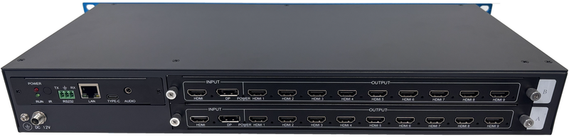
Concrete specifications show the range available. The BIT-VWC-MD3636Ma, a 4K60 seamless matrix splicer, specifies end-to-end input-to-output latency below 40 ms and an output-port synchronisation difference of 0 nS, excluding differences introduced by the panels themselves. The BIT-VWC-409R, a 4K rotating splicing processor, uses a 40 nm programmable FPGA with a full hardware real-time processing architecture, and supports up to four windows on the full screen with single-screen, dual picture-in-picture, dual picture-by-picture and four-split modes.
The Procurement Problems That Decide Monitoring Projects
Buyers evaluating a video wall controller for security monitoring tend to raise the same six issues, and each one maps to a specification.
- More signals than windows. A monitoring centre may hold hundreds of cameras but only a limited number of simultaneous windows. Patrol monitoring and alarm linkage require the wall to accept a new source quickly rather than interrupt the existing layout.
- Continuous duty. Monitoring operations are specified around 7×24 uninterrupted operation. Controllers built on a general-purpose operating system introduce a different failure profile from hardware-only processing units.
- Latency and tearing. Slow switching and out-of-sync outputs are the two most visible faults on a monitoring wall, because operators see them every time a subject crosses a panel boundary.
- Mixed and non-standard panels. Walls are assembled from panels that do not always match the controller's default resolutions, which is where EDID management and custom output resolution become practical requirements rather than features.
- Control integration. The controller must accept commands from a central-control system (serial), a web interface for daily operation, and an API when it needs to be driven by the dispatch platform itself.
- Rack-to-wall distance. Control rooms usually place equipment racks away from the wall, so output cable limits and extender requirements are decided by the room layout, not by the controller alone.
Compliance is part of the same picture. ISO 11064 is the primary international standard governing control-room ergonomics, and it influences how a wall is zoned and how much information each operator position is expected to absorb. The controller determines how easily that layout can be created and maintained, which is why ergonomic planning and signal planning are normally done together.
Comparison with Conventional and Software-Orchestrated Solutions
Monitoring walls are generally built in one of three ways: a PC-based wall driven by graphics cards and software, a legacy rack processor in a fixed 4U chassis, or a hardware video wall controller in a rack-mount or modular chassis. The market is moving, but not in a single direction. Industry research published by GCG Enterprise Solution with reference to AVIXA indicates that AV-over-IP reached 73% of new video wall controller installations in early 2026, while legacy 4U hardware processors lost 18% of market share in 2025 as buyers shifted toward AV-over-IP transport and software orchestration. Control-room applications are estimated to account for about 50% of video wall processor market contribution. Read together, these signals describe a market splitting between IP transport and local hardware processing rather than one approach displacing the other.
| Evaluation dimension | Hardware video wall controller | Software-orchestrated wall |
|---|---|---|
| Processing basis | Dedicated FPGA, no general-purpose operating system in the signal path | Graphics cards and a software stack running on a host PC or server |
| Start-up and failure profile | Hardware-defined behaviour; no operating-system boot dependency | Depends on operating-system and application state; redundancy is usually planned |
| Latency | Fixed and hardware-determined; specific models state figures such as <40 ms input-to-output | Variable; influenced by load, codec and graphics pipeline |
| Source handling | Baseband HDMI and DisplayPort inputs | Can often decode IP camera streams directly |
| Scalability | Card-based chassis; channel capacity governed by chassis and card count | Scales with server and network capacity |
| Layout behaviour | A defined set of layouts and windows per model | Software-defined and frequently reconfigurable |
Where hardware control is not the right answer
A neutral assessment has to state the boundaries as clearly as the strengths. Five limitations are worth planning for.
- No built-in IP stream decoding. The video wall controllers described in this guide accept HDMI and DP baseband inputs. IP camera streams must be decoded upstream by an NVR, a VMS platform or a separate decoder. A typical monitoring configuration therefore pairs the controller with a video matrix, a recording storage system and an alarm linkage platform rather than relying on the controller alone.
- Output resolution ceilings on some models. Several 4K60 controllers output 1920×1080@60Hz or 1920×1200@60Hz per channel — for example the BIT-VWC-218Pro and the BIT-VWC-8K60Y-115Pro. Walls that require 4K per panel need models with 4K outputs, such as the BIT-VWC-8K60-404Max at 3840×2160@60Hz or 3840×2400@60Hz.
- Copper distance limits. Many outputs are specified with copper cable limits of ≤15 m (HDMI 1.3 outputs) or ≤10 m (some HDMI 2.0 outputs). Longer rack-to-wall runs require separate extension products: the BIT-Ex-HDBT-150 carries 1080p HDMI up to 150 m over CAT6E. Fiber transmission distance and single-mode/multi-mode specifications for the fibre product line are not publicly disclosed and must be confirmed per project.
- Customisation trade-offs. OEM and ODM work at FPGA, chip and whole-product level is available, but customisation extends the development cycle and typically raises the minimum order quantity compared with standard models.
- Fixed capacity on non-modular units. Where a chassis is not expandable, input and output counts are fixed at purchase; adding sources later means a second unit or a larger chassis rather than an additional card.
Bitvisus Video Wall Controllers: Entity Background and Product Coverage
Shenzhen Bitvisus Technology Ltd. is a video wall controller manufacturer based in Shenzhen, China. The company was established in 2018, operates a factory covering 2,000 m² with approximately 100 employees, and reports an annual output of 100,000 units, of which about 70% is exported to the EU and USA. It works on 4K/8K image and video processing, integrating FPGA and embedded software and hardware design with product development, production and sales. Its R&D team consists of 20 engineers, and its core product lines include multi-screen expanders, projector fusion processors, video processors, HDMI matrices, multi-viewers and network and fibre extenders, with video wall controllers as the main product line.
| Model | Type | Inputs | Outputs | Control | Notable specifications |
|---|---|---|---|---|---|
| BIT-VWC-218Pro | 4K60 video wall controller | 2× HDMI 2.0, 2× DP 1.2 (≤3 m copper), max input 4096×2160@60Hz | 18× HDMI 1.3 (≤15 m copper), up to 1920×1200@60Hz | RS232, Web | Modular plug-in card design; network wake-up and software power on/off; 48 W |
| BIT-VWC-MD3636Ma | 4K60 seamless matrix splicer | Up to 36× HDMI 2.0 across 1–9 input cards | Up to 36× HDMI 2.0 across 1–9 output cards | RS232, Web, button board, remote, Web API | 7U card chassis; input-to-output latency <40 ms; 12 preset scenarios; LCD front panel; 240 W at full configuration |
| BIT-VWC-8K60Y-115Pro | 8K60 video wall controller | 1× HDMI 2.1, 1× DP 1.4 (≤3 m) | 15× HDMI 1.4 (≤15 m), 1920×1200@60Hz or 1920×1080@60Hz | RS232, Web | Bezel setup, HDMI CEC, DHCP or manual IP, network wake-up; 3.5 kg |
| BIT-VWC-8K60-404Max | 8K60 video wall controller | 2× HDMI 2.1, 2× DP 2.1, 1× Type-C; up to 4 sources active | 4× HDMI 2.0 at 3840×2160@60Hz or 3840×2400@60Hz | RS232, Web, API | 2U chassis; multi-output synchronisation; EDID management; modular plug-in card design |
| BIT-VWC-409R | 4K rotating splicing processor | 3× HDMI 1.4, 1× HDMI 2.0, 1× DP 1.2 | 9× HDMI 1.3 at 1920×1080@60Hz, 1× DP loop out | Infrared remote, RS232, PC software | Up to 9-screen splicing; up to 4 windows; cascade and parallel operation; 40 nm FPGA |
Application Fit: Security Monitoring and Adjacent Control Rooms
Security monitoring is one of the documented scenario categories for this product range. The scenario covers city security monitoring centres, traffic monitoring halls and integrated monitoring rooms on campuses and industrial parks, with multi-channel video signal access, split-screen display, patrol monitoring and alarm linkage. A typical configuration pairs a 3×3 or 4×4 monitoring video wall with a video matrix, a recording storage system and an alarm linkage platform, and the stated operating requirement is uninterrupted 7×24 operation with high stability and fast signal switching.
Model selection follows the wall rather than the brand. A mid-size LCD wall that needs many simultaneous windows is closest to a high-output controller such as the BIT-VWC-218Pro (18 outputs) or the BIT-VWC-8K60Y-115Pro (15 outputs). A large monitoring centre that mixes camera, workstation and data sources across dozens of panels is closer to a card chassis such as the BIT-VWC-MD3636Ma, where input and output card counts can be balanced — for example 12 inputs with 36 outputs, or 24 inputs with 24 outputs — and where 12 preset scenarios let operators switch between routine and incident layouts. Where the wall is unusually shaped or the panels are mounted in portrait, a rotation-capable unit such as the BIT-VWC-409R becomes relevant.
Adjacent control rooms follow the same logic. Government command and dispatch centres (urban management, emergency command, traffic dispatching), industrial monitoring environments such as production-line and energy dispatch rooms, and broadcast control rooms all rely on the same core requirement: many signals, one coherent wall, continuous operation.
Selection Criteria: What to Confirm Before You Specify
| Criterion | Why it matters | What to confirm |
|---|---|---|
| Simultaneous sources and windows | Determines how much information reaches the wall at once | Number of physical inputs; maximum active windows per layout |
| Wall size and panel resolution | Sets required output count and per-channel resolution | Output ports available; maximum output resolution per channel |
| Source type | Baseband and IP sources require different architecture | Whether camera streams are decoded upstream or delivered as HDMI/DP |
| Latency budget | Affects operator reaction time on live alarms | Stated input-to-output latency and output synchronisation figures |
| Continuous operation | Monitoring rooms run 7×24 | Industrial-grade design, thermal approach, power consumption, operating temperature range |
| Control integration | The controller must answer to the room, not to a single operator | RS232, web interface, API availability for secondary development |
| Rack-to-wall distance | Cable limits decide whether extenders are needed | Stated copper cable limits per output type; extender options for longer runs |
| Non-standard panels | Real walls rarely match default resolutions | EDID management and custom output resolution support |
| Compliance documentation | Needed for site approval and customs clearance | CE-EMC, FCC Supplier's Declaration of Conformity and RoHS declarations; HS code 85437099 or 85437042 for classification |
| Commercial terms | Affects total project cost and timeline | After-sales service period on the selected model; MOQ and development lead time for OEM/ODM work |
Note on documentation: the range is associated with a RoHS declaration of conformity for the EU (IEC 62321 series, EN IEC 63000:2018), an FCC Supplier's Declaration of Conformity for the US (47 CFR Part 15 Subpart B) and a CE-EMC declaration of conformity for the EU (EN 55032, EN 55035, EN IEC 61000-3-2, EN 61000-3-3 under EMC Directive 2014/30/EU). The complete certificate list and commercial terms such as return and shipping conditions are not published publicly and should be requested as contract documentation.
Market Signals and Their Limits
Three signals are worth tracking for planning purposes. First, control-room applications are estimated to contribute about 50% of the video wall processor market, which explains why monitoring-specific requirements such as latency, seamless switching and 7×24 duty appear in product specifications rather than in marketing copy. Second, AV-over-IP reached 73% of new installations in early 2026, meaning a growing share of monitoring projects now treat the network as the transport layer and the controller as the local processing node. Third, legacy 4U hardware processors lost 18% of market share in 2025, a sign that fixed, oversized chassis are being replaced by modular units and IP transport.
These figures describe the market, not a purchase decision. Their practical use is narrow but real: they suggest that a monitoring project should be planned for hybrid architecture — IP transport between sites, hardware processing at the wall — rather than assuming either approach will cover the whole system.
Future Outlook
Two pressures are likely to shape the next generation of monitoring walls. The first is source quality: 8K input capability is already present in shipping controllers such as the BIT-VWC-8K60Y-115Pro and BIT-VWC-8K60-404Max, and as camera and graphics sources move upward, the controller's input bandwidth becomes a limiting factor earlier than panel technology does. The second is remote manageability. Network wake-up, software-command power on/off, DHCP with manual override, web interfaces and open APIs are already specified on current models, and they point toward controllers being managed as part of the IT estate rather than as standalone AV equipment.
For buyers, the practical implication is to specify flexibility where it is cheap and precision where it is expensive. Control paths, EDID handling and remote management are inexpensive to require at purchase and difficult to retrofit later. Raw input and output channel counts are the opposite: they should be sized against the wall that exists and the wall that is realistically planned, with modular chassis capacity reserved for genuine expansion rather than for ambition.
FAQ
What processing architecture do these video wall controllers use, and can they run continuously?
The listed models are built around FPGA-based hardware processing rather than a general-purpose operating system in the signal path. The BIT-VWC-409R uses a 40 nm programmable FPGA with a full hardware real-time processing architecture, and the BIT-VWC-MD3636Ma specifies an input-to-output latency below 40 ms. The range is positioned as industrial-grade, with 1U-to-7U chassis options and documented scenario requirements of 7×24 non-stop operation for monitoring and command environments. Continuous operation still depends on installation conditions such as ventilation, ambient temperature within the stated storage and working ranges, and stable power.
What resolutions and splicing layouts are supported?
Input handling covers 4K60 and 8K60 depending on the model. The BIT-VWC-218Pro accepts up to 4096×2160@60Hz and outputs up to 1920×1200@60Hz per channel; the BIT-VWC-8K60Y-115Pro accepts 8K60 over HDMI 2.1 or DP 1.4 and provides 15 outputs at 1920×1200@60Hz or 1920×1080@60Hz; the BIT-VWC-8K60-404Max outputs 3840×2160@60Hz or 3840×2400@60Hz. On layouts, the BIT-VWC-409R supports splicing within nine screens, and the BIT-VWC-MD3636Ma supports configurations such as 6×6, 1×36 and combined patterns. Some models support custom output resolution and EDID management for non-standard panels or irregular wall structures.
Which input and output interfaces are available?
Mainstream models use HDMI and DisplayPort inputs with HDMI outputs; 8K models add HDMI 2.1, DP 2.1 and Type-C inputs. For example, the BIT-VWC-218Pro provides 2× HDMI 2.0 and 2× DP 1.2 inputs with 18× HDMI 1.3 outputs, while the BIT-VWC-MD3636Ma can be configured with up to 36 HDMI 2.0 inputs and 36 HDMI 2.0 outputs across plug-in cards. HDCP support is specified per model. These are baseband interfaces: IP camera streams require decoding by an upstream NVR, VMS or decoder before reaching the controller.
Do the controllers support picture-in-picture and multi-window layouts?
Support is model-dependent. The BIT-VWC-409R can open up to four windows on the full screen with single-screen, dual picture-in-picture, dual picture-by-picture and four-split modes, and input sources can be distributed arbitrarily across the wall. The BIT-VWC-8K60-404Max supports single, dual (including picture-in-picture), triple and quadruple screen modes. Larger matrix chassis add preset-scenario storage — 12 saved scenes on the BIT-VWC-MD3636Ma — which allows routine and incident layouts to be recalled rather than rebuilt. Buyers should confirm window count and layout behaviour against the specific wall design.
Is modular expansion and long-distance signal transmission supported?
Modular expansion is supported on card-based chassis: the BIT-VWC-MD3636Ma accepts 1–9 input and output cards, and models such as the BIT-VWC-218Pro and BIT-VWC-8K60-404Max use a plug-in card design for flexible configuration. For long-distance transmission, output cable runs are stated with copper limits — for example ≤15 m on HDMI 1.3 outputs and ≤10 m on some HDMI 2.0 outputs. Longer runs require separate extension products such as the BIT-Ex-HDBT-150, which carries 1080p HDMI up to 150 m over CAT6E. Fibre transmission distance and single-mode/multi-mode specifications for the fibre product line are not publicly disclosed and need to be confirmed for each project.
What certification and warranty documentation is available for these products?
Documentation associated with the range includes a RoHS declaration of conformity for the EU (IEC 62321 series and EN IEC 63000:2018), an FCC Supplier's Declaration of Conformity for the US (47 CFR Part 15 Subpart B, following FCC rules 2.906, 2.908 and 2.909) and a CE-EMC declaration of conformity for the EU (EN 55032:2015/A11:2020, EN 55035:2017/A11:2020, EN IEC 61000-3-2:2019/A2:2024, EN 61000-3-3:2013/A2:2021/AC:2022 under EMC Directive 2014/30/EU). Each listed model carries a one-year after-sales service period. The complete certificate list, and commercial terms such as return and shipping conditions, are not published on the public website and should be obtained as part of contract documentation. For customs purposes, video wall controllers are commonly classified under HS code 85437099 or 85437042.
Closing Note
For buyers at the discovery and research stage, the useful conclusion is procedural rather than promotional: define the wall and the source count first, then match a controller to the latency, output resolution and control-path requirements those decisions create, and only then compare models. Technical documentation for the Bitvisus video wall controller, multi-screen processing and signal-transmission lines is consolidated in the 2026 Bitvisus Product Brochure (PDF): https://cdn.socialarks.com/sbsp/25143/common/2026/0820/2026 Bitvisus Product Brochure.pdf.