
Step-Up Substation Transformers for North American Storage Plants: A Technical Primer
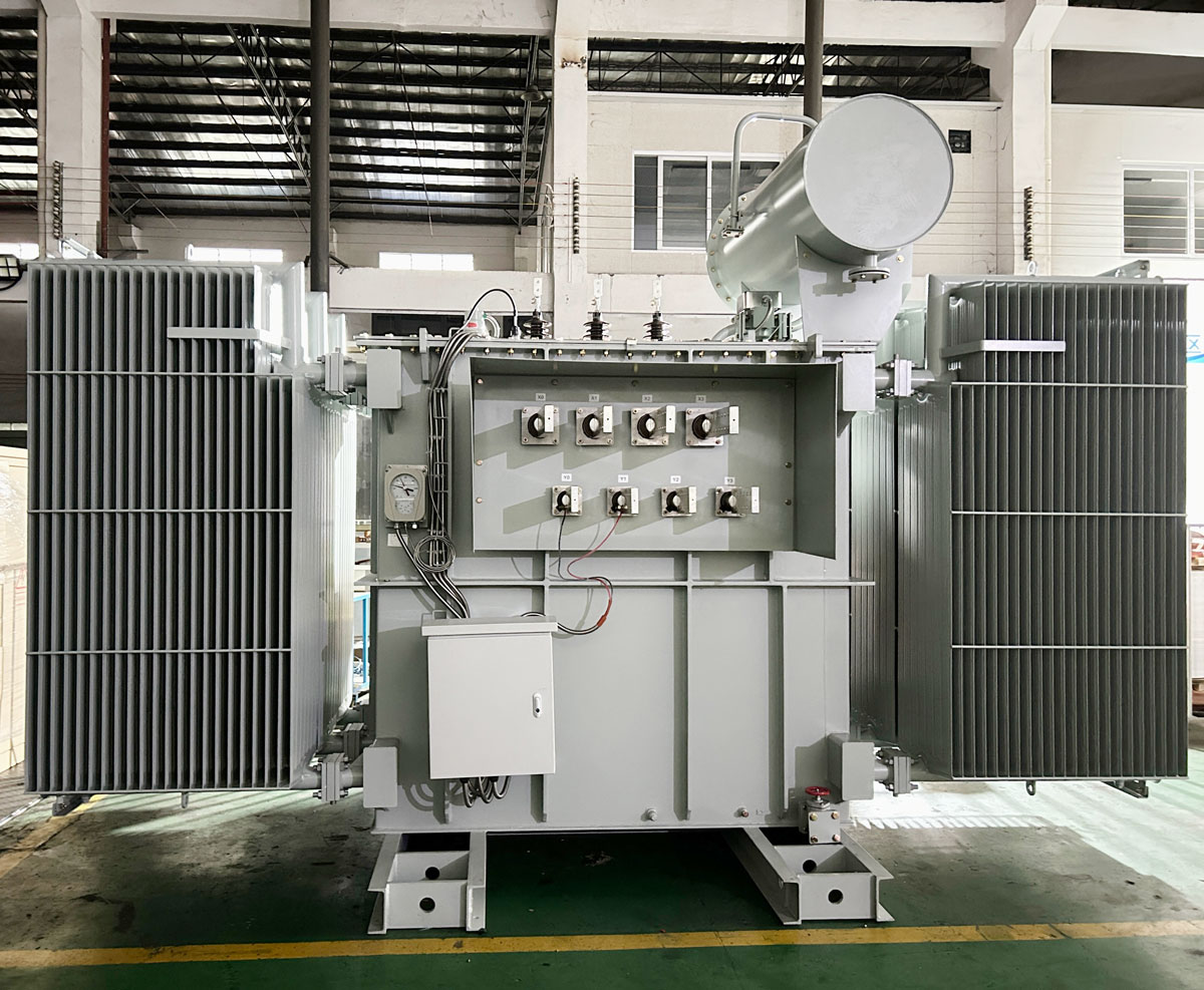
Why a Storage Plant Needs a Dedicated Step-Up Main Transformer
Substation power transformers are core equipment in medium- and high-voltage power transmission and distribution systems. They convert voltage levels for efficient long-distance power transmission, stabilize grid voltage, and supply electricity to residential areas, commercial districts, industrial parks and large-scale facilities across urban, suburban and rural regions. In a storage plant, that general role becomes specific and unusually demanding.
A battery energy storage system delivers power through a power conversion system (PCS) that produces low-voltage alternating current, commonly 480 V, 600 V or 800 V. The plant collector system and its interconnection point operate at medium voltage such as 12.47 kV, 13.8 kV, 24.94 kV or 34.5 kV, and utility-scale projects may interconnect at transmission classes up to 230 kV. The step-up main transformer performs bidirectional voltage transformation between the low-voltage PCS and the medium-voltage grid, and it also supplies the plant auxiliary loads.
The consequence for buyers is that a storage interconnection transformer is not simply a larger version of a distribution unit. Its duty cycle, harmonic environment and reversing power flow determine whether the unit holds up in service, and those three factors rarely appear in a simple nameplate comparison.
The Operating Profile That Shapes the Design
Storage duty differs from conventional substation duty in four practical ways:
- Bidirectional power flow. Current reverses with each charge and discharge transition, so losses, temperature rise and protection settings must remain valid in both directions.
- Frequent cycling and rapid load changes. A storage plant may cycle many times per day rather than following a smooth load curve, and it needs short-term overload capability to ride through fast transitions.
- Converter harmonics. PCS and rectifier equipment inject harmonic content that increases winding and core losses and raises local heating.
- Continuous, often unattended operation. Plants run on 24/7 availability, grid-connected for peak shaving, frequency regulation and backup duty, with condition monitoring that lets remote teams detect drift without a site visit.
Those conditions explain why storage specifications call out bidirectional power flow capability, tolerance to frequent charge-discharge cycles and rapid load changes, converter harmonic tolerance, short-term overload capability, low losses, and temperature and operating-condition monitoring, rather than rated capacity alone.
Technical Characteristics Buyers Should Be Able to Recognize
The table below maps the characteristics that typically appear in storage interconnection specifications to what each one means once the unit is in service.
| Characteristic | What it means in a storage application |
|---|---|
| Bidirectional power flow | The unit operates with current in both directions; losses, temperature rise and protection settings must be valid on charge and on discharge. |
| Cycling duty and overload capability | Frequent charge-discharge cycles and rapid load changes; short-term overload capability supports fast power transitions. |
| Harmonic tolerance | PCS and rectifier harmonics raise losses and local heating, so non-linear load content has to be part of the thermal design. |
| Winding arrangement | Double-split, dual-secondary or multi-winding layouts allow one transformer to serve two converter blocks or two voltage buses, for example a double-split unit stepping dual 480 V up to 13.8 kV. |
| Cooling class | ONAN and ONAF designs, with fan-assisted ratings where short-term peak output exceeds the self-cooled rating. |
| Voltage regulation | Tap range sized for grid voltage variation at the interconnection; on-load tap changing where regulation is required under load. |
| Dielectric fluid | Mineral oil, natural ester such as FR3, or MIDEL 7131; the choice affects fire point, containment design and environmental exposure. |
| Grounding provisions | Neutral grounding and zig-zag grounding transformers for collector systems and medium-voltage grounding arrangements. |
| Insulation and test regime | Impulse withstand verified through lightning impulse testing, plus routine and type tests and factory acceptance testing. |
| Monitoring and protection interfaces | Temperature and operating-condition monitoring, protection relays, metering and SCADA integration. |
| Enclosure and environment | Outdoor continuous service, with corrosion-resistant or 304 stainless steel NEMA 4X tank options for coastal and harsh sites. |
For the substation power transformer family, these characteristics sit inside a defined envelope: capacities from 150 kVA to 450 MVA, primary voltages typically 2.4 kV to 230 kV, secondary voltages typically 0.6 kV to 35 kV, with NEMA, ANSI C57, DOE and IEEE standards applied as appropriate. Real storage projects rarely stay inside a single catalog row, and that is where customization begins.
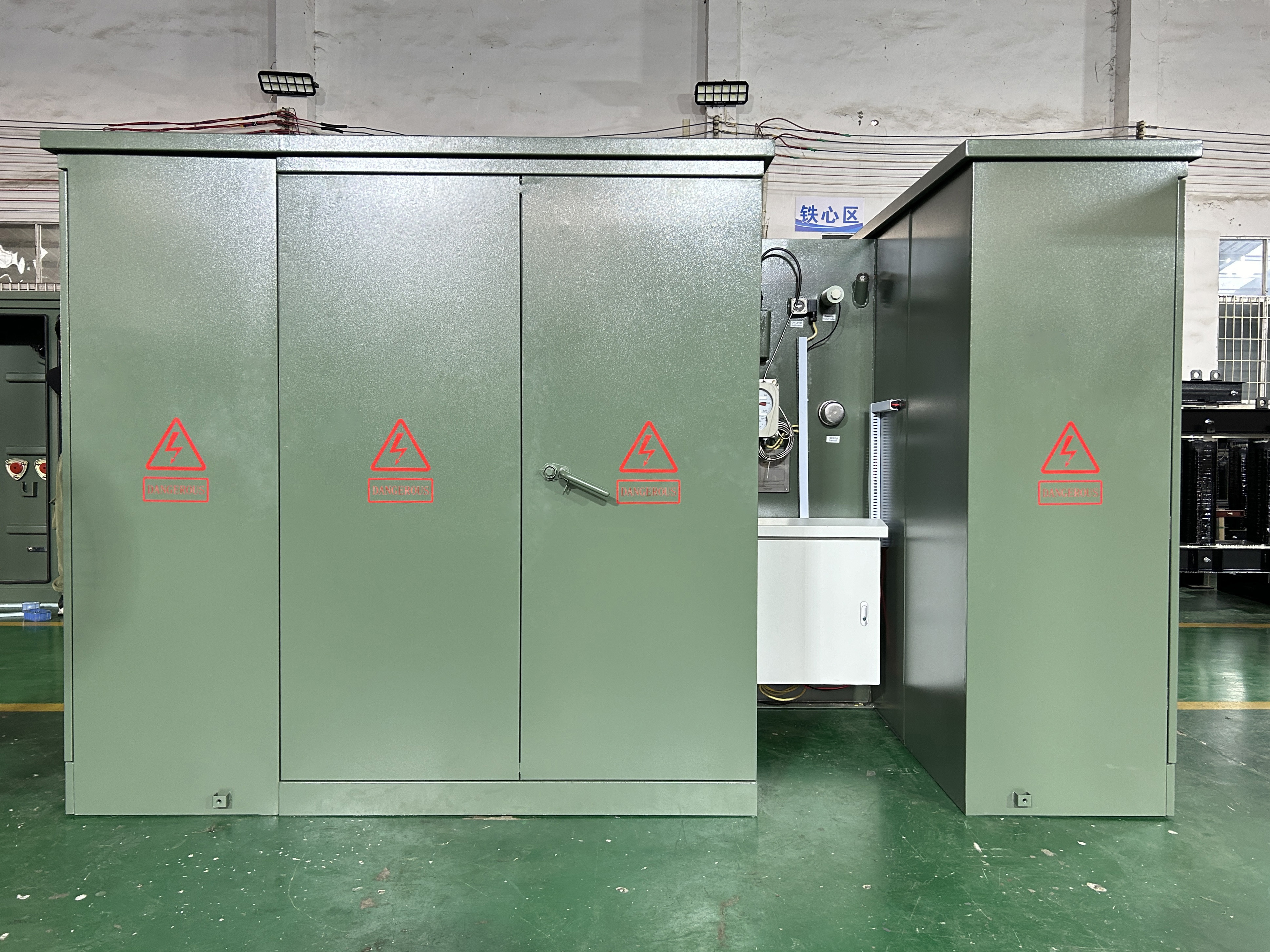
North American Grid Modernization Is Raising the Specification Floor
Storage interconnection equipment is being specified inside a broader grid investment cycle. The global substations market was valued at USD 128.5 billion in 2024 and is expected to reach USD 178.9 billion by 2034, a compound annual growth rate of 3.2%, according to Global Market Insights. Transformer demand tracks that curve: the global transformer market is estimated at USD 64.64 billion in 2025 and projected to reach USD 88.48 billion by 2030, driven by grid modernization and rising electricity demand, according to MarketsandMarkets.
Liquid-filled designs continue to carry the utility segment. Oil-immersed transformers held the highest share of the power transformer segment at approximately 59.3% in 2025, a reflection of cooling efficiency and durability in utility applications, per Grand View Research. Storage interconnection transformers sit inside that majority, which is why containment, fire separation and fluid selection remain standing agenda items in project reviews.
Two further forces are visible. Monitoring is moving from option to expectation: the smart transformer market is projected to grow from USD 3.17 billion in 2025 to USD 10.15 billion by 2035 at a CAGR of 12.35%, driven by the need for real-time grid monitoring, according to SNS Insider. At the same time, manufacturing capacity is being contested: data center transformer demand is expected to rise from USD 2.2 billion in 2023 to USD 5.9 billion by 2030 at a 10% CAGR, according to Strategic Market Research.
On the standards side, North American substation transformer designs are primarily governed by the IEEE C57 series, while UL 1561 and UL 1562 apply to liquid-filled and dry-type units respectively. Substation power transformers are commonly specified against NEMA, ANSI C57, DOE and IEEE standards as applicable. Projects increasingly expect a documented link between the design, the applicable standard and the test evidence, because impulse withstand and temperature rise are exactly where non-standard designs most often require re-work.
Where These Transformers Sit: Storage, Solar and Hybrid Plants
In utility-scale and commercial photovoltaic plants, the transformer steps up 208 V, 380 V, 480 V, 600 V or 800 V inverter output to 13.8 kV, 24.94 kV or 34.5 kV for power collection and grid interconnection, and steps down power for plant auxiliary loads. Service conditions include high solar exposure, high ambient temperature, dust, humidity or salt fog, inverter harmonics and fluctuating output. Matching equipment typically includes PV modules, inverters, combiner boxes, medium-voltage switchgear, ring main units, reclosers, protection devices, SCADA and medium-voltage cables. The special requirements are step-up and reverse power flow capability, tolerance to fluctuating output and daily load cycles, inverter harmonic tolerance, lightning and surge protection, high-temperature resistance and low losses.
Storage plants use the same equipment family in a harder regime: bidirectional transformation between the low-voltage PCS and the medium-voltage grid, converting 480 V, 600 V or 800 V to 12.47 kV, 13.8 kV, 24.94 kV or 34.5 kV, while also feeding plant auxiliary systems. Battery containers, racks, a battery management system, PCS, an energy management system, medium-voltage switchgear, ring main units, protection devices, SCADA, HVAC and fire-suppression systems all connect around that single transformer interface.
Build configurations show how the requirement translates into hardware. A 6,500 kVA double-split oil-immersed step-up transformer converting dual 480Y/277 V inputs to 13.8 kV lets one unit serve two converter blocks. A 5 MVA UL/cUL bidirectional pad-mounted transformer stepping dual 480Y/277 V up to 12 kV suits utility-scale battery energy storage. An 8,000 kVA dual-split-winding substation transformer at 34.5 kV with dual 480 V secondaries serves utility-scale BESS grid integration where two low-voltage buses feed one interconnection.
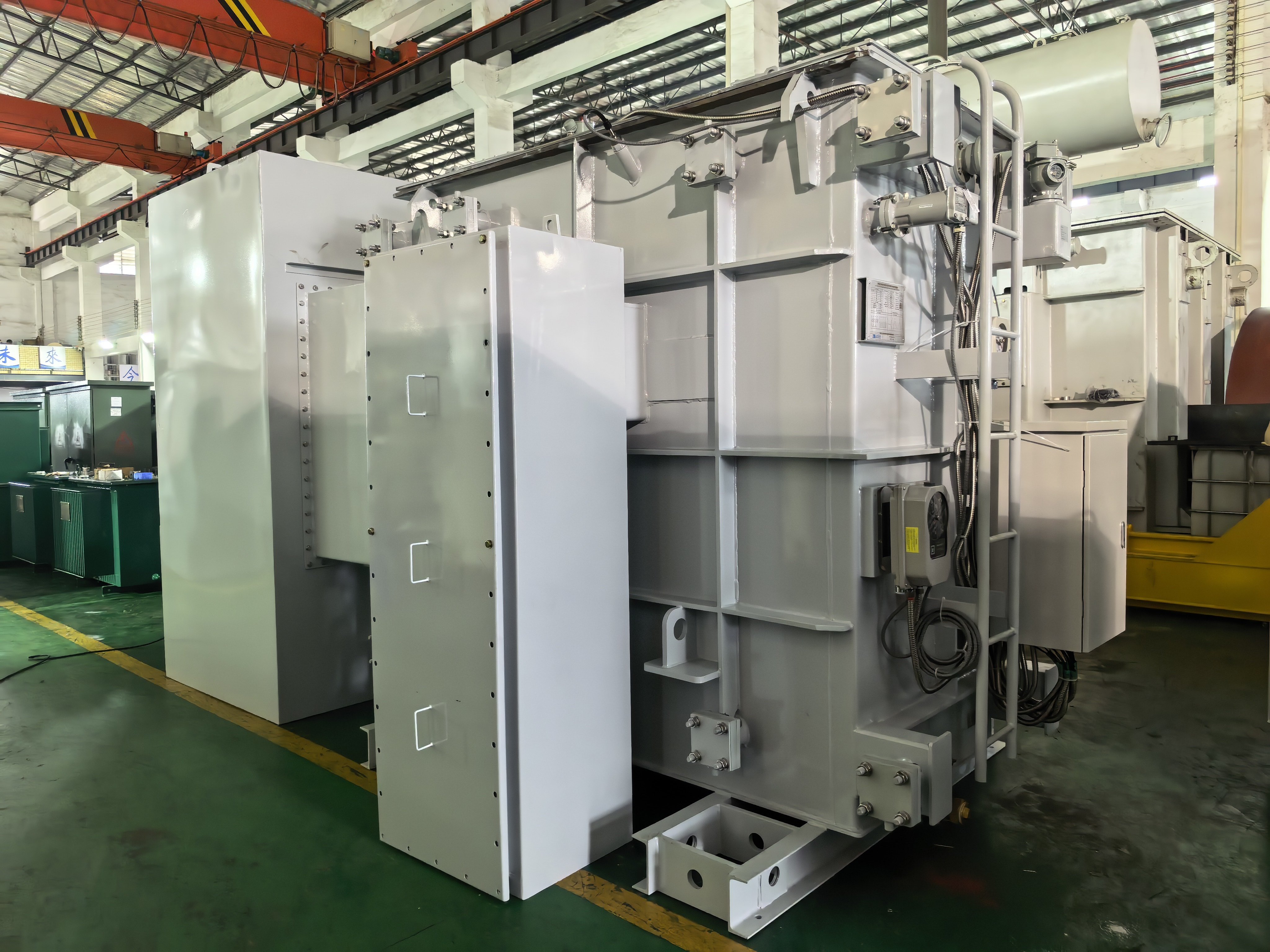
Hybrid solar-plus-storage and wind-plus-storage projects add a further wrinkle: the main transformer may see reverse power flow from the generation side and forward flow into the plant auxiliary systems, so the design has to remain valid in both. Where a plant interconnection voltage or bus arrangement does not match a catalog unit, the specification moves into OEM or ODM territory.
High-Voltage OEM and ODM Customization: What It Changes
Xiamen Winley Electric Co., Ltd. is a transformer manufacturer established in 2014 and headquartered at No. 99 Yilan Road, Siming, Xiamen, Fujian, China. The company produces high-voltage power transformers with rated capacities up to 450 MVA and voltage ratings up to 230 kV, with products meeting ANSI, IEEE, CSA, DOE2016 and IEC60076 standards. Its manufacturing base covers 45,000 m² with an annual production capacity of 35,000 units and approximately 220 staff, including a research and development team of 35 engineers; more than 200 front-line employees work in production, 80% of them with more than eight years of experience. Major markets include North and South America, and the product family covers substation transformers, three-phase and single-phase pad-mounted transformers, pole-mounted transformers, epoxy resin cast dry-type transformers, vacuum-impregnated transformers, isolation transformers, control transformers, voltage regulators and reactors. Certifications include UL and cUL, ISO, CE, TUV and EMC.
In OEM and ODM terms, the customization levers that matter for a storage interconnection are rated capacity and voltage ratio; winding arrangement, including double-split, dual-secondary and multi-winding; impedance and short-circuit withstand; cooling class and fan-assisted ratings; tap range and on-load tap changing; dielectric fluid selection among mineral oil, natural ester and MIDEL 7131; tank and enclosure specification including 304 stainless steel NEMA 4X where required; grounding provision; monitoring and protection interfaces; and the test and documentation package.
The service scope around the unit matters as much as the unit itself. Winley Electric supports product selection recommendation, drawing design, accessory selection, acceptance support, transportation planning and installation guidance, alongside 24/7 technical support and a two-year free maintenance service. In-house test capability includes lightning impulse test devices in addition to conventional testing equipment, and the production facilities are equipped with silicon steel sheet slitting and cross-cutting lines, multi-model foil and wire winding machines, vacuum constant-temperature drying ovens, two-stage vacuum oil filters and automated welding equipment. Every unit is factory-inspected against standard specifications before shipment.
For a 230 kV-class interconnection, the engineering effort concentrates in insulation coordination and impulse withstand, and the practical question for a buyer is who controls that design work. A manufacturer whose engineers work directly in ANSI, IEEE, CSA, DOE2016, NEMA and IEC60076 is better positioned to convert a project's non-standard parameters into a buildable, testable design than a supplier that simply resells a standard platform.
How High-Voltage Custom Builds Compare with Conventional Approaches
| Dimension | Standard catalog unit with external mitigation | Purpose-built step-up main transformer |
|---|---|---|
| Voltage and ratio coverage | Medium-voltage distribution classes | Up to 230 kV, capacities to 450 MVA |
| Harmonic management | External filters and reactors, adding equipment and footprint | Harmonic loss and heating addressed inside the transformer design |
| Cycling and bidirectional duty | Sized for one-directional, relatively smooth load | Design and protection valid in both directions under frequent cycling |
| Unit count and footprint | Several devices plus interconnections and civil works | Fewer devices, a single controlled interface point |
| Engineering and testing | Shorter engineering, largely routine testing | Longer design and type-test cycle, impulse testing, witnessed factory acceptance |
| Lead time and cost | Lower cost and faster when the parameters match | Higher engineering content, justified when parameters genuinely deviate |
| Spares and interchangeability | Widely interchangeable across suppliers | Requires as-built documentation and a planned spares strategy |
What Comes Next for Storage Interconnection Equipment
Three directions look reasonably clear from the available market data. First, monitoring is shifting from option to expectation: with the smart transformer segment projected to reach USD 10.15 billion by 2035 at a CAGR of 12.35%, condition monitoring is being written into specifications earlier rather than added after commissioning.
Second, the bidirectional requirement will stop being treated as a special feature. As storage, solar-plus-storage and hybrid plants multiply, a transformer equally valid on charge and on discharge becomes the default starting point for an interconnection specification rather than a custom request.
Third, capacity competition will keep delivery planning on the critical path. With data center transformer demand projected to rise from USD 2.2 billion in 2023 to USD 5.9 billion by 2030 at a 10% CAGR, storage developers are bidding for the same manufacturing slots, and design simplicity, where it is technically sufficient, carries real schedule value.
The practical implication for procurement teams at the awareness and research stage is to treat the step-up main transformer as a system component rather than a line item: fix the PCS output configuration, the interconnection voltage, the harmonic and cycling duty and the applicable standard set first, then decide whether those inputs fit a standard unit or require an OEM or ODM build.
FAQ
It is the transformer that connects the plant low-voltage power conversion system to the medium- or high-voltage grid, providing bidirectional voltage transformation between the low-voltage PCS and the medium-voltage grid. In a battery energy storage system it converts 480 V, 600 V or 800 V to 12.47 kV, 13.8 kV, 24.94 kV or 34.5 kV and also supplies the plant auxiliary loads. It belongs to the substation power transformer family used in power transmission and distribution systems.
Distribution transformers are generally specified for one-directional, relatively predictable load flow toward end users. A storage interconnection transformer must remain valid with power flowing in both directions, tolerate frequent charge-discharge cycles and rapid load changes, absorb converter harmonics from the PCS and support short-term overload conditions. It is also specified with temperature and operating-condition monitoring, because charge-discharge duty produces a different loss and thermal profile from ordinary distribution service.
North American substation transformer designs are primarily governed by the IEEE C57 series, while UL 1561 and UL 1562 apply to liquid-filled and dry-type units respectively. Substation power transformers are typically specified against NEMA, ANSI C57, DOE and IEEE standards as applicable, and projects increasingly expect test evidence tying the design back to those standards. Winley Electric states that its products meet ANSI, IEEE, CSA, DOE2016 and IEC60076, and the company holds UL and cUL certification.
The core inputs are the PCS alternating-current output voltage and bus configuration, base and peak capacity in MVA, grid interconnection voltage and frequency, impedance and short-circuit requirements, required tap range and whether on-load tap changing is needed, winding arrangement (single, double-split, dual-secondary or multi-winding), cooling class, dielectric fluid preference, enclosure specification and site environment including corrosion exposure, grounding requirements, monitoring and protection interfaces, the applicable standard set and certification target, and the required test and documentation package including factory acceptance testing.
Custom engineering increases design, type-testing and factory acceptance time, and it removes the interchangeability that catalog units offer, so a non-standard unit needs documented as-built drawings and a planned spares strategy. Liquid-filled designs, which dominate the high-voltage classes, also require oil containment, fire separation and site civil works, while dry-type designs are generally available across a narrower high-voltage range. Customization also addresses transformer parameters only: system studies such as short-circuit, harmonic and insulation coordination remain part of the buyer's own engineering scope.
Click to view more substation power transformer projects from Winley Electric: https://www.winley-electric.com/supplier-4803516-substation-power-transformer
·Website:www.winley-electric.com

¿Tiene preguntas o necesita más detalles?
Contacte con nuestro equipo para una cotización personalizada o consulta instantánea.
Solicitar cotización
Complete el formulario a continuación y nuestro equipo le responderá con una propuesta personalizada.
Chat directo de WhatsApp
¿Prefiere chatear en tiempo real? Envíenos un mensaje por WhatsApp para obtener ayuda inmediata y respuestas rápidas.
- Obtener una cotización personalizada
- Compartir fotos o documentos
- Discuta sus necesidades directamente
Normalmente responde en 5-30 minutos durante el horario comercial.