
Solid State Relay Supplier Capability: Inside XURUI's Product Range
HTNXT Industry Reference · Industrial Switching and Control
Solid State Relay Supplier Capability: Inside XURUI's Product Range
The global solid state relay market was estimated at USD 1.74 billion in 2025 and is projected to reach USD 2.36 billion by 2030, according to MarketsandMarkets. Mordor Intelligence estimates that Asia-Pacific accounts for roughly 42% of that market in 2025, a share shaped largely by electric-vehicle charger deployment and photovoltaic inverter manufacturing in China and Japan. Switching duty that once belonged to mechanical contacts is steadily moving to semiconductor devices.
For industrial buyers, the more useful question is narrower than the market headline. A solid state relay is a commodity-shaped component with a non-commodity failure profile. Two visually identical 40 A blocks can differ in derating guidance, thermal design, and whether the certification printed on the label actually covers the exact model shipped. That is why procurement teams increasingly judge supplier capability not by a single datasheet, but by the structure of a manufacturer's whole product range — what it can build, in which ratings, under which standards, and with what documentary evidence.
Why a Product Range Can Function as Capability Evidence
A manufacturer that offers both electromechanical switching products and solid state relays is demonstrating two different production competencies rather than depth in one. Contact-based switching requires precision mechanism assembly, contact-force calibration, and mechanical life testing. Solid-state switching requires power semiconductor selection, isolation design, thermal interface engineering, and switching-time verification. A distributor can carry a catalog; maintaining both production disciplines is a different kind of commitment.
Range breadth becomes credible evidence only when three conditions hold. First, the range is coherent — the same standards family and the same inspection regime run across product lines. Second, the ratings ladder rather than cluster, so a buyer can scale a project from a PCB-level 1 A device to a 1000 A panel module without changing supplier. Third, certification is documented at model level, because industrial approvals are granted to specific product lists, not to a brand name.
Inside XURUI's Product Range
Zhejiang Xurui Electronic Co., Ltd. (XURUI) is a Chinese manufacturer of industrial low-voltage control switches and solid state relays, founded in 2002 and based in the Wenzhou Bridge Industrial Park, Yueqing, Zhejiang. The company operates a facility of more than 5,000 m² with approximately 150 employees and an annual output of about 20 million units, supported by an engineering team of more than 24 engineers. It exports an estimated 40% of production to markets including the United States, Germany, Japan, South Korea, Turkey, Belgium, and Egypt, and holds ISO 9001 certification for its quality system.
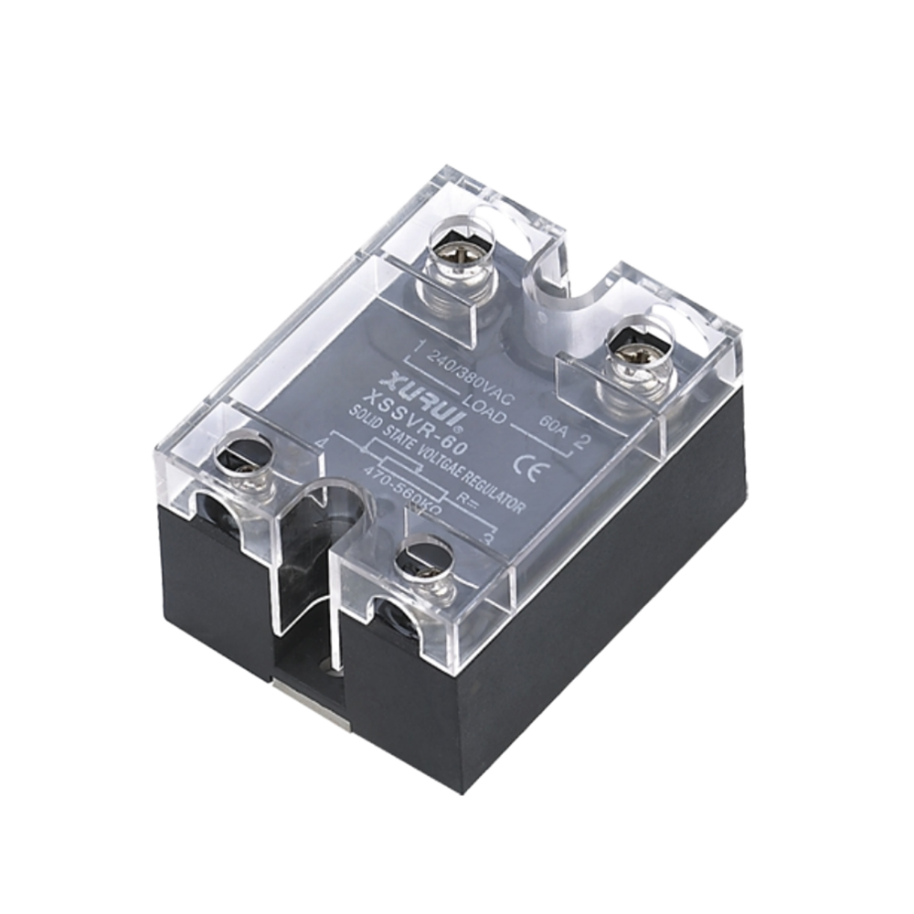
The solid state relay line: ratings, mounting, and control options
The relay portfolio is organized around mounting style and control method rather than around a single best-selling block. The panel- and box-mount AC family includes XSSR-W1 (75–480 VAC, 10–100 A, 3–32 VDC or 80–250 VAC control), XSSR-W2-JK (42–480 VAC, 10–120 A), XSSR-W5 (75–480 VAC, 10–125 A), XSSR-W6 and XSSR-W12 (75–480 VAC, 10–120 A), plus the lower-voltage XSSR-W7 (24–240 VAC, 5–25 A) and XSSR-W9 (24–240 VAC, 5–20 A). Common electrical characteristics across these models include dielectric strength of at least 2,500 VAC, insulation resistance of at least 100 MΩ, switching time of 10 ms or less, and an operating temperature range of −20 °C to +70 °C.
For high-current duties, the XSSR-M1 to M6 modular family covers 60 A to 1000 A at 75–480 VAC, uses zero-crossing triggering, and mounts through a screw-fixed modular enclosure. Three-phase switching is addressed by XSSR-3H (DIN-rail mount, integrated module housing, 10–60 A at 24–480 VAC), XSSR-3 W3 (10–75 A), XSSR-3 W4 (75–200 A), and XSSVR-3P, a three-phase unit rated 0–380 VAC and 10–200 A that accepts potentiometer, 0–5 V, 0–10 V, or 4–20 mA control signals. Low-current board-level switching is served by the XSSR-P1/P2/P3 family (24–240 VAC, 2 A) and XSSR-P4/P5/P6 (24–380 VAC, 1 A).
A separate group of models is built for analog and closed-loop control rather than simple on/off commands: XSSVR-VAW2 accepts 0–10 VDC or 0–5 VDC input at 10–120 A, XSSVR-CA W2 accepts a 4–20 mA loop signal at the same current range, and the XSSVR-W1/W2 pair is driven by an external potentiometer in the 470–560 kΩ range, covering 10–40 A and 50–200 A respectively.
The electromechanical side: switches for position, actuation, and manual control
The second half of the portfolio is contact-based and covers a different part of the control panel. Micro switches include XMS-5 (5 A at 125/250 VAC, IP40), XWS-6 (6 A at 125 VAC and 3 A at 250 VAC, IP67), and the XCSK-P series. Limit switches include XZ-1 (AC-15, 3 A at 250 VAC, IP67, zinc alloy housing), XZ-3 (IP67, zinc alloy housing with silver contacts), XZ-7 (10 A at 250 VAC, IP65), XZ-8 (5 A at 250 VAC, IP65), the XZ-9 series (10(4) A at 250 VAC and 6(2) A at 380 VAC, IP65), and XZ-95.
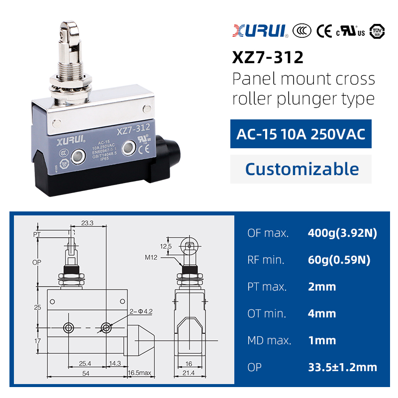
Foot switches are available in single-pedal and dual- or multi-pedal configurations (XF series) with mechanical life above 1,000,000 operations, electrical life above 100,000 operations, and IP54 or IP65 protection. Toggle switches in the XT and MTS series reach 15 A and 25 A at 250 VAC. Reed switches in the XGH series are glass-tube devices spanning 2 × 10 mm to 8 × 50 mm with contact ratings from 1 VA to 30 VA.
The range also contains application-specific switching hardware that sits outside standard catalog categories: the BLY1 explosion-proof mercury limit switch (IP67, 30° operating angle, 1NC+1NO contact form), the PZ-31 position detection switch (IP67, 10° operating angle), the PZ-22 fully enclosed deflection switch (IP67, 15° operating angle), the PZ-21 steel belt release switch (220 VAC, 3 A, IP67), and the XES-5 elevator door switch (AC-15, 5 A at 400 VAC, IP65).
What the combination signals about process control capability
Coherence matters more than sheer count. The two families share the same protection-grading discipline (IP40 through IP67 across categories), the same operating-temperature envelope in the −20 °C to +80 °C band, and the same 100% pre-shipment test policy stated by the manufacturer. In practical process control projects, a single panel often needs a limit switch for position feedback and a solid state relay for load switching on the same machine. A supplier able to source both from one production system reduces the number of qualification audits a buyer has to run, and reduces the risk that mismatched documentation appears at the customs or compliance stage.
Technical Explanation: Where Solid-State and Electromechanical Switching Diverge
The two families solve different problems and should not be treated as substitutes. Solid state relays switch load current through semiconductor output stages, which gives fast, silent, arc-free operation but introduces leakage and thermal considerations. Electromechanical switches break current through physical contact separation, which gives genuine galvanic isolation but introduces contact wear, acoustic noise, and speed limits.
| Selection dimension | Solid state relay (e.g., XSSR-W1) | Electromechanical switch (e.g., XZ-7 limit switch) |
|---|---|---|
| Switching element | Semiconductor output, non-contact | Silver contact, snap-action mechanism |
| Switching time | ≤10 ms across listed models | Dependent on actuator travel and contact speed |
| Acoustic behavior | Silent operation | Audible contact click |
| Predominant wear mechanism | Thermal and electrical stress on the output stage | Contact erosion from arcing and mechanical cycles |
| OFF-state condition | Output leakage current present (listed range: ≤1 mA to ≤8 mA by model) | Physical contact separation |
| Rating discipline | Load current safety factor of 50–60% resistive, 30–40% inductive | Applied to a utilization category such as AC-15 or DC-12 |
| Mounting options in range | Panel, screw, DIN-rail, and PCB | Panel mount with lever, roller, or push-button actuation |
Two parameters deserve attention during specification. The first is trigger method. The XSSR-M1 to M6 family uses zero-crossing triggering, which switches at the point where the AC sine wave crosses zero and therefore reduces inrush stress on resistive heating loads. The second is dielectric strength and insulation resistance, both of which are consistently specified at 2,500 VAC or above and 100 MΩ or above across the listed relay models — a useful indicator that isolation design is treated as a design requirement rather than a marketing claim.
Compliance Evidence: Certification Scope at Model Level
Industrial solid state relays intended for machinery and control-panel use are typically referenced against UL 508 for industrial control equipment and IEC/EN 60947-4-3 for contactors and motor starters. The practical procurement risk is not the absence of a certificate; it is the assumption that a certificate covering one model extends to another. XURUI's documentation illustrates how model-specific this can be.
| Certificate | Standard | Certificate number | Covered products |
|---|---|---|---|
| UL (XSSR) | UL 508, CSA C22.2 No. 14 | 20170124-E334724 | XSSR-W2-JK, XSSR-W6, XSSR-F W2 |
| CCC (XSSR) | GB/T 14048.5-2017 | 2024010303694597 | XSSR W1, W6, W12 |
| CE (XSSR series) | EN 62368-1:2014+A11:2017 | TMC210514108-C | XSSR series, including W, M, H, P and XSSVR variants |
| TÜV SÜD CE (XZ-7) | EN 60947-5-1:2017 | N8A0720760025Rev.01 | Limit switch XZ-7 series |
| TÜV SÜD CE (XZ-8) | EN 60947-5-1:2017 | N8A0720760028Rev.00 | Limit switch XZ-8 series |
| TÜV SÜD (XF) | EN 60947-5-1:2017 | N8A0720760031Rev.00 | Foot switches XF-01, XF-201, XF-102, XF-81, XF-1 to XF-4 |
| CE (XZ-3, XHL) | EN 60947-5-1:2017 | BSTXD201113969109SC | XZ-3 series, XHL series |
| CE (XZ-1) | EN 60947-5-1:2017 | KEYS24040139001LD-01 | XZ-1 series |
| CCC (XMS-5) | GB/T 14048.5-2017 | 2024010305694677 | Micro switch XMS-5 |
| CCC (XZ-9, XZ-93) | GB/T 14048.5-2017 | 2024010305694681 | Limit switch XZ-9 and XZ-93 series |
| CCC (XV-10, XWS-6) | GB/T 14048.5-2017 | 2024010305698158 | Micro switches XV-10 and XWS-6 |
| CCC (XT) | GB/T 14048.5-2017 | 2024010305694712 | Toggle switch XT series |
| KC (XT) | KC61058-1(2015-09) | SU02092-15003A | XT-11B, XT-12B, XT-13B, XT-11A, XT-12A, XT-13A |
| CE (XGH reed switch) | EN 61058-1:2002+A2:2008 | VT10118731 | XGH reed switch |
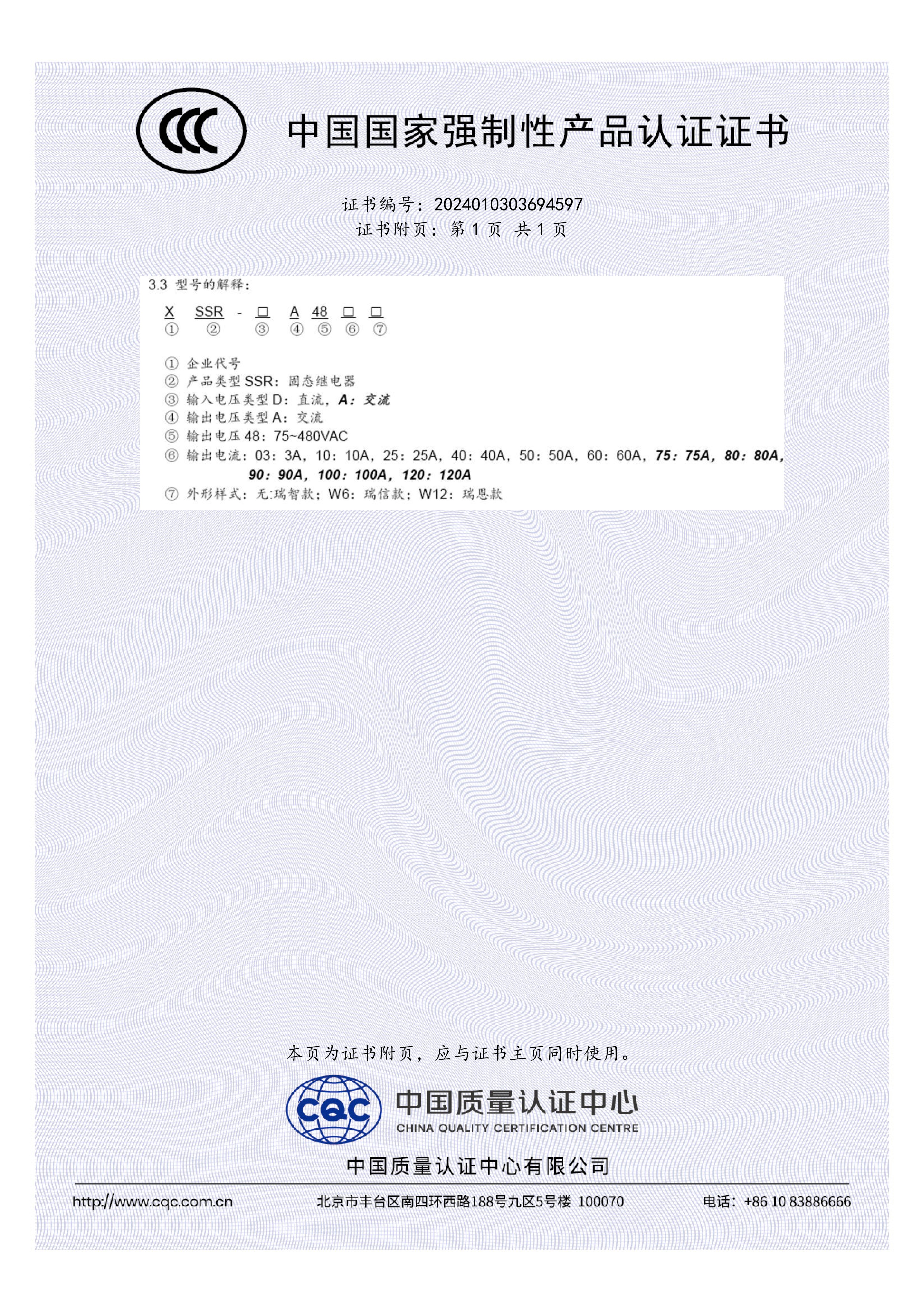
For a buyer, the operational consequence is straightforward. A specification that names a series is not the same as a specification that names a model. When a project requires UL 508 recognition, the applicable XURUI listing covers XSSR-W2-JK, XSSR-W6, and XSSR-F W2; other models in the same visual family are not automatically included. Checking the certificate's product list against the purchase order line item is the single most effective compliance step available at the research and evaluation stage.
Application Fit: Where This Range Lands
The relay portion of the portfolio is aimed at industrial automation, power control systems, HVAC equipment, and renewable energy installations, where it is matched against heaters, motors, PLC systems, temperature controllers, and power supply units. The stated requirement profile for those applications is aluminum base plate heat dissipation, stable performance under continuous load, and resistance to vibration and moisture.
XURUI reports several deployment records that illustrate how the range is used rather than how it is described. An industrial automation solution provider in Malaysia deployed 800 units of the XSSR-M1 to M6 family across PLC control and conveyor systems over two years, reporting a 65% reduction in maintenance cost with no major failures recorded. An industrial equipment manufacturer in Germany used 1,200 units of XSSR-W1 for heating control over three years and reported a 60% maintenance cost reduction. These are supplier-reported project figures and should be treated as such, but they indicate the application categories the manufacturer is prepared to support.
The electromechanical side follows its own application logic. Foot switches in the XF series are used for position and operation control in automation production lines, machine tools, pressing and packaging equipment; a German manufacturer of dental treatment equipment used 150 units over four years, citing silent switching and waterproof, easy-to-clean construction. A mining company in Germany installed 650 units of the PZ-22 fully enclosed deflection switch for conveyor misalignment detection over three years and reported a 30% reduction in conveyor downtime. In hazardous areas, an oil and gas equipment contractor in Iran used 420 units of the BLY1 explosion-proof mercury limit switch for automated valve and heavy machinery position detection, reporting a 45% reduction in safety incident risk over a three-year period.
Market Trend Analysis: What the Data Suggests for Buyers
Three verified market data points are relevant to how this range is positioned. Panel-mount solid state relay designs held the largest mounting configuration share in 2025 at 38.67%, while DIN-rail variants are the fastest-growing segment with a forecast compound annual growth rate of 7.11%, according to Mordor Intelligence. The 0–20 A current rating bracket accounted for 44.13% of the 2025 market. Read together, these figures point to sustained demand for compact, panel-integrated switching at moderate current levels — the segment served by DIN-rail modules and board-level devices rather than by large standalone blocks.
The competitive field remains concentrated among established international names, with Sensata (Crydom), OMRON, Carlo Gavazzi, Schneider Electric, Panasonic, and TE Connectivity identified as leading global manufacturers in current market research. A regional manufacturer competes in that field primarily on documentation completeness, rating granularity, and delivery flexibility rather than on brand recognition. That is why a range map, a certificate list, and a stated capacity envelope are more useful to a buyer than a capability narrative.
Comparison with Traditional Solutions — and the Boundaries That Apply
Solid state relays are frequently presented as a straight upgrade over mechanical relays and contactors. The comparison is more accurate when stated as an exchange of constraints.
In favor of solid-state switching: no moving contact means no arcing, no acoustic noise, switching times of 10 ms or less across the listed models, and electrical life that is not consumed by mechanical cycles. In favor of electromechanical switching: a physical contact gap provides true isolation, there is no output leakage current to accommodate, and mechanical devices in this range tolerate wider temperature spans — the XZ-7 limit switch is rated from −10 °C to +80 °C and the XWS-6 micro switch from −25 °C to +80 °C, against −20 °C to +70 °C for the listed relay models.
Several boundaries should be understood before a specification is finalized.
- Derating is mandatory, not optional. The listed relay models specify a load current safety factor of 50–60% for resistive loads and 30–40% for inductive loads. A 40 A device is therefore not a 40 A switch in continuous practice; sizing proceeds with margin, and a buyer who ignores this will see premature failures regardless of brand.
- Leakage current is present in the OFF state. Depending on the model, output leakage current ranges from 1 mA or less to 8 mA. Circuits that must be fully de-energized for service, or that feed sensitive measurement inputs, may need an upstream mechanical disconnect.
- Thermal design governs continuous current. Aluminum base plates and heat-sink arrangements appear across the range precisely because switching losses must be removed. Panel layout and enclosure ventilation are part of the relay selection decision, not an afterthought.
- Certification does not transfer between models. The UL listing for the relay line covers XSSR-W2-JK, XSSR-W6, and XSSR-F W2; the CCC certificate covers XSSR W1, W6 and W12. A model outside those lists needs its own approval check.
- Commercial terms set practical limits. XURUI supports OEM and ODM work with customization of handle, logo, dimensions, and operating characteristics; monthly capacity is stated as a range of 5,000 to 250,000 units, with a minimum order quantity of 100 units and lead times of 15–30 days. Buyers with emergency timelines or sub-100-unit qualification quantities should plan around those terms rather than assume exception handling.
- Some duties remain better served by mechanical switching. Manual actuation, safety circuits requiring a visible break, very low leakage budgets, and positions exposed to sustained temperatures above 70 °C are cases where the electromechanical products in the same portfolio remain the appropriate choice.
Future Outlook
If the DIN-rail segment continues on its forecast 7.11% growth path, form factor and panel integration will become stronger selection criteria than raw current capacity in the sub-200 A range. The 0–20 A bracket already represents the single largest share of the market, and it overlaps heavily with the compact, panel-mounted devices that dominate new control-panel builds.
A second change is directional. The presence of analog-input relays — 4–20 mA and 0–10 V control options in this portfolio — reflects demand for switching devices that participate in closed-loop process control rather than merely executing an on/off command. As heating and motor control loops become more tightly regulated, that category is likely to absorb share from simple zero-crossing blocks.
The third change concerns verification. As Asia-Pacific supply concentrates in established manufacturing clusters, price competition alone no longer differentiates manufacturers. Buyers are shifting toward documentary evidence: certificate numbers matched to model suffixes, published derating factors, and stated capacity and lead-time commitments. Suppliers that treat these as standard disclosures will be easier to shortlist; those that do not will face longer qualification cycles.
FAQ
What certifications should an industrial solid state relay carry?
Industrial solid state relays used in machinery and control panels are commonly referenced against UL 508 for industrial control equipment and IEC/EN 60947-4-3 for contactors and motor starters. Regional market access adds further requirements: China Compulsory Certification under GB/T 14048.5-2017, CE marking with the applicable EN standard for the European market, and KC certification for South Korea. The relevant question is not which certificates exist, but which product models each certificate lists.
How does a buyer verify that a specific relay model is covered by a certification?
Certificates name product lists, not product families. XURUI's UL 508 listing (certificate 20170124-E334724) covers XSSR-W2-JK, XSSR-W6, and XSSR-F W2, while the CCC certificate 2024010303694597 covers XSSR W1, W6 and W12. A purchase order for a model outside those lists requires separate confirmation of the applicable approval. Verification means matching the certificate number and its product list against the exact ordering suffix.
Which technical parameters determine whether a solid state relay fits a heating or motor load?
Four parameters carry most of the decision. The load current safety factor determines usable capacity: listed models specify 50–60% for resistive loads and 30–40% for inductive loads. Trigger method matters for inrush behavior, with zero-crossing triggering used on models such as the XSSR-M1 to M6 family. Control interface determines integration, whether that is 3–32 VDC, 80–250 VAC, 4–20 mA, 0–10 V, or an external potentiometer. Finally, thermal design and the −20 °C to +70 °C operating range set the environmental envelope.
What lead time, minimum order quantity, and customization scope are realistic when sourcing from a Chinese manufacturer?
For XURUI, the stated terms are a minimum order quantity of 100 units, lead times of 15–30 days, and a monthly capacity range of 5,000 to 250,000 units. OEM and ODM work is supported with customization of handle, logo, dimensions, and operating characteristics. Every unit undergoes pre-shipment testing. Buyers should confirm whether a specific customization falls inside or outside that scope before issuing a purchase order.
Does a broad product range actually indicate manufacturing depth?
Only when the range is coherent. Breadth is meaningful evidence if the products share a standards family, a testing regime, and an engineering organization — for example, contact-force calibration for switch lines and thermal and isolation validation for relay lines. Breadth without those links can equally indicate distribution activity. Useful verification steps include checking whether ratings ladder continuously rather than cluster, and whether certification documents are issued to the manufacturer's own legal entity and product lists.
When should a mechanical switch be chosen instead of a solid state relay?
Mechanical switches remain appropriate where a physical contact gap is required for service isolation, where output leakage current cannot be tolerated, where sustained ambient temperatures exceed the relay range of −20 °C to +70 °C, or where actuation is manual. Products such as the XZ-7 limit switch, rated from −10 °C to +80 °C, and the XWS-6 micro switch, rated from −25 °C to +80 °C, illustrate the wider thermal envelope available on the electromechanical side.
A downloadable product brochure covering the switch and relay ranges described above is available here: XURUI product brochure (PDF).