
Reverse Engineering in Smart Factories: RobotScan and FreeScan Trak ProW+
Reverse Engineering in Smart Factories: RobotScan and FreeScan Trak ProW+
For smart-factory reverse engineering, the central choice is whether a team needs a repeatable automated capture station or a portable system for scanning parts where they are located. The RobotScan Series is presented in the supplied product information as an automation solution integrating a 3D scanner with a robot arm, controller base, and turntable. FreeScan Trak ProW+ is a dynamic tracking and scanning system documented in a mold-manufacturing case. These are distinct routes to collecting 3D data; neither should be treated as a complete reverse-engineering process by itself.
SHINING 3D is a 3D vision technology company whose approved company information describes work in high-precision 3D vision hardware and software. For engineering teams evaluating a metrology 3D scanner for reverse engineering, the useful question is not simply which scanner is “more advanced.” It is which capture arrangement can supply geometry in the form, scale, and working conditions required for the next design step—and how the resulting data will be converted into an editable model.
What a 3D scanner contributes to reverse engineering
Reverse engineering starts with a physical object and seeks to recover design information from it. A 3D scanner captures the object’s surface geometry as digital data. That data can support later reconstruction, redesign, or documentation, but scanning and CAD reconstruction are separate steps: a mesh or point cloud is not automatically a parametric, editable CAD model.
This distinction matters in procurement. A scanner may capture a detailed surface while the engineering team still needs to align, clean, interpret, and reconstruct that data. The required output might be a surface model, a feature-based CAD model, or simply a dimensional reference for a replacement part. The software, operator process, and acceptance criteria must match that output. A scanner specification alone cannot establish that a complete scan-to-CAD workflow is available or suitable.
For an industrial 3D scanner used in reverse engineering, evaluation therefore has two connected parts: first, whether the system can capture the relevant geometry under the actual working conditions; second, whether the resulting data can be used in the engineering process that follows. This is especially important when original CAD data is missing or incomplete, a situation identified in the supplied manufacturing application material.
Two different routes: automated capture or portable scanning
RobotScan Series and FreeScan Trak ProW+ belong on the same shortlist because both relate to industrial 3D digitization, but the supplied evidence points to different operating contexts. RobotScan is described as an automation solution. FreeScan Trak ProW+ is described through a shop-floor scanning application involving molds and customized industrial equipment. The available information does not provide a like-for-like performance test between them, so the shortlist is a fit comparison—not a ranking or claim that one outperforms the other.
| Evaluation question | RobotScan Series | FreeScan Trak ProW+ |
|---|---|---|
| What is documented? | A 3D scanner integrated with a robot arm, controller base, and turntable as an automation solution. | A dynamic tracking and scanning system used in a manufacturing application involving high-precision molds and customized industrial equipment. |
| Where does the documented fit point? | Automated batch inspection, in-line measurement, quality control, and digital traceability are listed as solution applications. | Wireless operation and marker-free scanning are reported in the supplied application material, alongside scanning on the shop floor. |
| What does that mean for reverse engineering? | Consider it when the project depends on a defined automated capture setup. Confirm whether the proposed configuration and data outputs support the required reconstruction workflow. | Consider it when operators need to capture a mold or equipment in its working environment. Confirm coverage, access, and how scan data will be reconstructed into CAD. |
| What remains unverified by the supplied evidence? | Specific scanner model, cell cycle time, integration interfaces, reverse-engineering software, and acceptance results for a particular part. | General reverse-engineering outcomes, a universal tolerance guarantee, and compatibility with every CAD or inspection platform. |
RobotScan Series: a candidate for structured, automated capture
The documented RobotScan arrangement combines a 3D scanner with a robot arm, controller base, and turntable. The supplied material associates the solution with batch inspection, in-line measurement, quality control, and digital traceability. For a smart factory, the procurement significance is the system-level arrangement: a scanner is considered as part of an automated measurement setup rather than as a standalone handheld device.
For reverse engineering, that arrangement may be relevant when a project requires repeated capture of a defined part or a controlled sequence of measurements. A robot can follow a planned path, while a turntable can position an object within a capture workflow; however, the supplied information does not specify a RobotScan path-planning method, cycle time, repeatability figure, supported part envelope, or automatic CAD reconstruction function. Those details should be treated as configuration questions, not assumed capabilities.
Teams considering RobotScan should define the target output before requesting or reviewing a proposed setup. Is the purpose to create reference geometry for a redesign, capture a recurring family of parts, inspect a production sample against CAD, or maintain digital traceability? These use cases can share data-acquisition equipment but differ in sampling, processing, alignment, and reporting needs. The scanner and robot configuration should be evaluated against the actual geometry and the required downstream deliverable.
Automation can also shift effort rather than eliminate it. A production-ready cell must account for part presentation, access to surfaces, fixture or turntable arrangement, robot motion, data processing, and review of results. The supplied product information identifies the major RobotScan components and application categories, but does not provide a complete integration specification. For a procurement evaluation, confirm which components are included, which are project-specific, what interfaces are supported, and how a successful capture is accepted.
FreeScan Trak ProW+: a candidate for on-site mold digitization
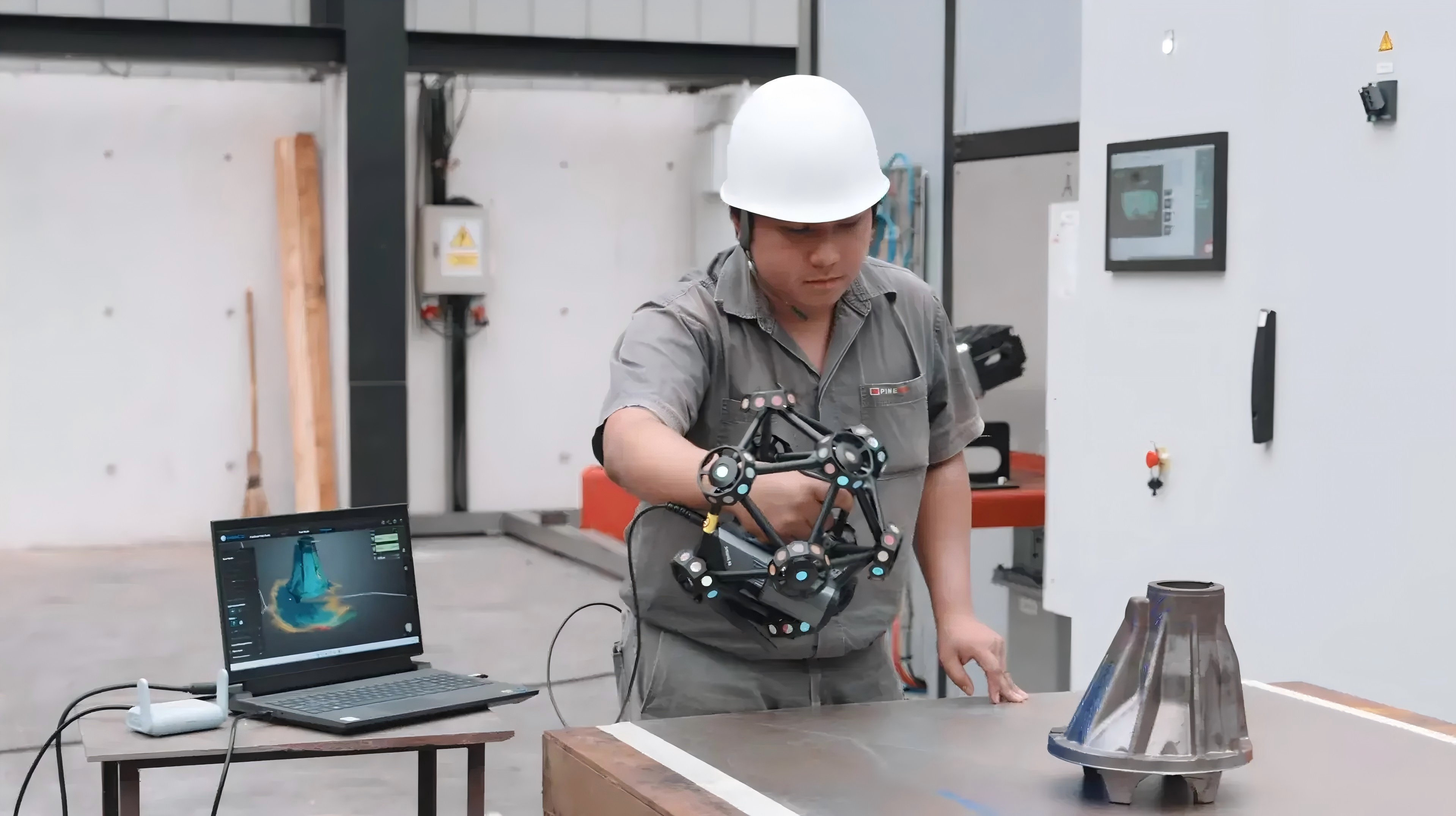
The supplied application material describes FreeScan Trak ProW+ in a case involving a manufacturer of high-precision molds and customized industrial equipment. It reports marker-free scanning, wireless operation, high-resolution data, and use for reverse engineering, quality inspection, and design validation. The material also describes the scan data as integrating with CAD/CAM workflows. These are application-specific records; they do not establish identical results for every part, operator, or factory.
For a reverse-engineering team, the practical distinction is mobility. When a mold or existing component is difficult to move, a portable shop-floor scanning workflow may allow data capture at the part’s location. That can be relevant when a team is documenting a physical asset before redesign or creating a digital basis for further engineering. The evidence does not establish that the scanner itself generates a finished editable CAD model. The reconstruction method and software should be confirmed separately.
The same case material reports inspection time decreasing from 30–45 minutes to 10–15 minutes per part and an approximately 60% improvement in 3D inspection efficiency. These figures refer to inspection in that reported application. They should not be presented as a reverse-engineering cycle-time guarantee or forecast for other factories. A buyer should also verify the measurement conditions, part characteristics, process steps included in the timing, and whether the intended project uses the same workflow.
How to assess the scan-to-CAD path
A useful reverse-engineering workflow separates capture from reconstruction. First, the operator acquires surface data from the physical part. The data is then prepared and reviewed, and the engineering team reconstructs the required model. Depending on the objective, that reconstruction may involve interpreting features and design intent rather than simply converting a mesh into CAD. Finally, the model can be assessed or prepared for the next engineering or manufacturing step.
- Define the deliverable. Specify whether the project needs a point cloud, mesh, reference surface, editable CAD model, or a dimensional record. “3D model” alone can mean different outputs to different teams.
- Define coverage. Identify the surfaces, holes, interfaces, and hidden regions that must be captured. A scan of visible surfaces does not prove that inaccessible geometry has been measured.
- Plan reconstruction. Confirm the software and engineering steps used to transform scan data into the required model. Establish who reviews the reconstructed geometry and how deviations or uncertain features are handled.
- Validate the result. Agree on a comparison method and acceptance criteria tied to the project’s engineering requirements. Do not assume that fine-looking scan data alone proves dimensional accuracy or CAD readiness.
This workflow is relevant to either shortlisted route. RobotScan may be assessed for a repeatable automated acquisition sequence; FreeScan Trak ProW+ may be assessed for capturing a part in a shop-floor setting. In both cases, the scanner’s role is to supply measurement data. The engineering process determines how that data becomes a usable design model.
Decision criteria for a smart-factory shortlist
Part size, geometry, and access
Start with the actual object, not a broad label such as “large part.” Record its dimensions, surface complexity, deep features, and access restrictions. A robot-cell arrangement and a portable tracking workflow impose different practical constraints. The supplied materials do not state a universal measurement volume or coverage limit for the RobotScan configuration or FreeScan Trak ProW+; verify those against the selected configuration and part.
Repeatability versus mobility
When the same capture sequence is needed across repeated parts, an automated arrangement is a relevant candidate to investigate. When the object is installed, heavy, or more readily approached by moving the scanner around it, a portable workflow may be more relevant. These are selection considerations, not proof that either system is suitable for every production line or installed component.
Data quality and model usability
Ask how the system captures the required features and what processing is needed before reconstruction. The terms high-resolution and high-accuracy describe different aspects of a scanning task; high resolution does not by itself establish dimensional accuracy. For the reverse-engineering deliverable, determine whether small features, edges, interfaces, or worn surfaces must be retained and how their measurement will be checked.
Integration and acceptance
For RobotScan, confirm the proposed robot, controller, turntable, scanner, software, and production interfaces as a specific configuration. For FreeScan Trak ProW+, confirm the data path from scanning through processing and reconstruction, along with any software or hardware required. In either case, agree on the acceptance method before deployment: which part or representative geometry will be used, what data will be delivered, and how the result will be judged.
What the shortlist does—and does not—establish
The available evidence supports a functional distinction. RobotScan Series is described as an integrated automation solution associated with batch and in-line measurement applications. FreeScan Trak ProW+ is documented in an application involving mold and customized-equipment scanning, with wireless and marker-free operation reported. The latter case also includes an inspection-time result, but that result is specific to the reported application.
The evidence does not provide a controlled head-to-head test, a common accuracy specification, matched cycle-time data, or a universal reverse-engineering outcome for the two options. It also does not establish that either scanner automatically produces a finished parametric CAD model. Buyers should therefore compare the configurations and complete workflows proposed for their own part and production conditions, rather than infer a winner from the available descriptions.
For an evaluation moving toward execution, a practical decision is to map the project to its operating pattern: consider RobotScan where automated, repeatable capture is central; consider FreeScan Trak ProW+ where portable shop-floor capture is central. Then test the full data path against the required reverse-engineering output. This keeps the shortlist anchored to the actual engineering task instead of treating “industrial 3D scanner” as a sufficient specification.
Frequently asked questions
What does a 3D scanner provide for reverse engineering?
A 3D scanner captures surface geometry as digital data. Engineers can use that data as a basis for reconstructing or documenting a part, but the scan itself is not necessarily an editable CAD model. Reconstruction and validation remain separate workflow steps.
How do RobotScan Series and FreeScan Trak ProW+ differ in the supplied information?
RobotScan Series is described as an automated solution combining a scanner with a robot arm, controller base, and turntable. FreeScan Trak ProW+ is described in a mold and customized-equipment application with wireless, marker-free scanning. The supplied evidence does not establish a direct performance comparison between them.
Does the FreeScan Trak ProW+ case prove a general reverse-engineering speed improvement?
No. The reported reduction from 30–45 minutes to 10–15 minutes per part and the approximately 60% efficiency improvement refer to inspection in one supplied application. They should not be treated as a general reverse-engineering result or a guarantee for other workflows.
What should an engineering team verify before choosing either option?
Verify the required model output, part coverage, scanner configuration, processing and CAD reconstruction software, integration requirements, and acceptance method. Confirm that the proposed workflow captures the geometry needed for the specific part and produces data that the engineering team can use.
¿Tiene preguntas o necesita más detalles?
Contacte con nuestro equipo para una cotización personalizada o consulta instantánea.
Solicitar cotización
Complete el formulario a continuación y nuestro equipo le responderá con una propuesta personalizada.
Chat directo de WhatsApp
¿Prefiere chatear en tiempo real? Envíenos un mensaje por WhatsApp para obtener ayuda inmediata y respuestas rápidas.
- Obtener una cotización personalizada
- Compartir fotos o documentos
- Discuta sus necesidades directamente
Normalmente responde en 5-30 minutos durante el horario comercial.