
Rebar Coupler Fit Across Four Project Types
Rebar Coupler Fit Across Four Project Types
Choosing a rebar coupler for a high-rise building, airport, high-railway station, or bridge starts with the connection process and the reinforcement dimensions—not the project label alone. The available product information identifies rolling couplers, pressing couplers made from Q355B carbon steel, and one-touch couplers made from 40CR alloy steel, alongside equipment for threading, pressing, cutting, and tightening. These facts help define a preliminary fit; they do not establish that any model has been approved for a particular project or meets its structural requirements.
CANGZHOU BARTECH CONSTRUCTION MATERIAL CO., LTD. supplies rebar couplers and related rebar processing equipment. Its documented product range includes coupler models covering sizes from 16 to 40, a pressing machine for 16–32 mm rebar, threading machines for 16–40 mm rebar, and equipment for other stated size ranges. The practical selection question is how a coupler’s material, model dimensions, and required preparation equipment align with the project specification and the bar sizes to be connected.
Begin with the connection method and bar size
The strongest initial distinction is whether the proposed system uses a threaded connection or a pressing connection. A rolling coupler is specified for reinforcement connection and has model designations from 16 through 40. A separate pressing-coupler series also covers sizes 16 through 40, while its associated CBT32 pressing machine is specified for 16–32 mm rebar. A one-touch coupler is listed in models from 16 through 40 and is made from 40CR alloy steel. Those series labels identify available size designations; they do not by themselves demonstrate interchangeability among connection methods or machines.
For threaded systems, the rebar ends must be prepared using a compatible process and the specified thread details. The rolling-coupler data lists a 60-degree thread angle across the models, with thread specifications varying by model. For example, model 16 is listed as M16.5 × 2.5 and model 40 as M40.2 × 3.0. The published overall dimensions also vary: outer diameter is listed from 24 to 59 mm and length from 42 to 95 mm across the range. These details make model-by-model matching important; a nominal rebar size alone is not a complete thread or dimensional specification.
For a pressing system, the product series and the machine’s capacity must be checked separately. The Q355B pressing coupler series lists sizes φ16 through φ40, but the CBT32 pressing machine is listed for rebar from 16 to 32 mm. On the supplied specifications, the machine’s stated range does not cover the full coupler-series range. A project requiring a size above 32 mm therefore needs equipment coverage confirmed for that size; the available CBT32 data should not be read as a 16–40 mm machine specification.
Documented coupler types and dimensions
The table summarizes the product distinctions that can be established from the supplied specifications. It is a reference for narrowing a model request, not a performance ranking or confirmation of project approval.
| Coupler option | Documented material and range | Key dimensional or thread details | Selection point |
|---|---|---|---|
| Rolling rebar coupler | 45# carbon steel; 40CR alloy steel is also listed. Models 16–40. | 60° thread angle; model-specific threads. Outer diameter 24–59 mm and length 42–95 mm across models. | Confirm the exact model, thread specification, bar size, and threading-machine setup. |
| Pressing rebar coupler | Q355B carbon steel. Sizes φ16–φ40. | For φ16: 30 mm outer diameter, 110 mm length, 4.5 mm thickness. For φ40: 70 mm outer diameter, 240 mm length, 11.0 mm thickness. | Match the coupler size to a pressing machine with documented coverage for the required bar. |
| One-touch rebar coupler | 40CR alloy steel. Listed designations include φ11–16 and φ16 through φ40. | For φ16: 40 mm outer diameter and 106 mm length. For φ40: 83 mm outer diameter and 200 mm length. | Check the exact designation and dimensions against the design and connection instructions. |
The full pressing-coupler specification provides intermediate dimensions as well. For example, φ20 is listed at 36 mm outer diameter, 120 mm length, and 5.5 mm thickness; φ25 at 45 mm, 150 mm, and 7.4 mm; and φ32 at 56 mm, 192 mm, and 9.0 mm. The φ36 entry lists 63.2 mm outer diameter, 220 mm length, and 11.3 mm thickness. Because the specifications are size-specific, procurement documents should name the required size and dimension set rather than refer only to “a pressing coupler.”
One-touch coupler dimensions likewise change with designation. Examples include φ22 at 51 mm outer diameter and 133 mm length, φ32 at 70 mm and 170 mm, and φ36 at 78 mm and 190 mm. The listing also includes a φ11–16 designation; it should not be assumed to mean the same thing as the separate φ16 model. Buyers should preserve the manufacturer’s exact size designation on drawings, orders, and inspection records.
High-rise buildings: connect thread preparation to the selected coupler
For high-rise work, the scenario information describes rebar connection using threaded bar ends prepared by a rebar threading machine, followed by assembly with a coupler. Rolling couplers are one documented option for high-rise buildings, and the available models span 16–40. The process mapping makes threading equipment relevant to the coupler choice: the thread geometry and length required by the connection need to correspond to the actual machine setup and the selected model.
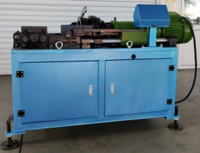
Two documented threading-machine options cover 16–40 mm rebar. The CBT40L has a 5.5 kW main motor, 380 V / 50 Hz rated supply, quick and slow speed ratios of 1:23 and 1:29, and maximum threading length listed as 100 mm or 200 mm depending on configuration in the product specification. Its listed dimensions are 1210 × 610 × 1120 mm and its net weight is 420 kg. The 40AO is an automatic-type threading machine for 16–40 mm rebar. Its maximum threading length is 90 mm with the block or 150 mm without the block; its listed dimensions are 1950 × 700 × 1120 mm, and net weight is 860 kg.
These specifications help a buyer compare the documented working range, threading length, and equipment footprint. They do not establish which machine is more productive on a particular site or whether either configuration meets a project’s production schedule. Before selection, confirm the required thread length, the applicable machine configuration, power supply, available installation space, and the project’s rebar and coupler drawings. The supplied high-rise scenario also identifies ISO and CE certificates as special requirements. That statement describes a scenario requirement; it is not evidence that a specific product or company holds either certificate.
Airports: keep coupler dimensions and equipment coverage visible
Airport projects appear among the stated applications for rolling, pressing, and one-touch couplers, as well as for the listed processing equipment. The useful distinction is therefore not an unsupported claim that one coupler is specifically “for airports,” but whether the selected connection type, bar size, dimensions, and preparation equipment match the airport project’s drawings and procurement requirements.
A rolling connection can be considered where the project specifies the relevant threaded-coupler arrangement and the model’s thread details match the required bar connection. The supplied rolling data identifies 45# carbon steel as the primary material and 40CR alloy steel as an alternative, with a 60-degree thread angle and model-dependent thread specifications. A Q355B pressing coupler offers a separate documented material and dimensional series, but the CBT32 machine’s stated rebar capacity ends at 32 mm. A 40CR one-touch coupler is another listed option, with its own model designations and dimensions. These descriptions define product attributes, not a project engineer’s approval of any particular connection.
For tightening work, the BOC torque-wrench models have different listed coverage. The BOC 8-32 is specified for 8–32 mm rebar, has a maximum torque value of 350 N·m, a no-load speed of 0–75 r/min, and a 6.0 Ah, 21 V battery. The BOC 8-42 specification describes 12–40 mm rebar and couplers in the 16–32 range, with a maximum torque value of 400 N·m. These ranges should be read as stated for each model; the wider rebar range of the BOC 8-42 does not mean its stated coupler range also extends to 40. Confirm the project’s connection procedure and wrench compatibility rather than inferring it from the model name.
High-railway stations: distinguish upsetting, cutting, and assembly
The high-railway scenario describes a sequence involving upsetting, thread cutting, and assembly of a rebar coupler. The equipment mapping names an upsetting machine and a thread-cutting machine. This is a process distinction: the coupler is the connection component, while the machines prepare the bar ends for the specified connection. Selecting a coupler without checking the required preparation steps leaves an important part of the system undefined.
The MQ40 is listed as a rebar thread-cutting machine, with a stated rebar size range of M14–M45 and a maximum thread length of 100 mm. Its main motor power is 5.5 kW; the listed supply options are 380 V / 50 Hz or 415 V / 50 Hz. Its overall dimensions are 1630 × 780 × 1100 mm. The product data classifies it under the rebar upsetting machine category while describing its function and name as a thread-cutting machine. For procurement and equipment schedules, use the model and the explicit machine function rather than treating the category label as a second machine function.
The 50S automatic upsetting machine has separate size coverage depending on the stated rebar grade: 16–50 mm for 400 rebar and 16–40 mm for 500 rebar. Its main motor power is 11 kW, rated supply is 380 V / 50 Hz, maximum pressure is 31.5 MPa, and listed net weight is 1200 kg. The 36S is specified for 16–36 mm 400 rebar and 16–32 mm 500 rebar. Those grade-dependent ranges matter when matching machine and material schedules; the machine range should not be reduced to one universal size claim.
The scenario material notes CE and ISO certificates as special requirements for high-railway work. Treat these as project requirements to verify against the applicable tender and approval documents. Product specifications alone do not prove certificate status, compliance, or acceptance for a railway project. A technical submittal should identify the exact coupler and machine models, the rebar grade and size, the connection method, and whatever supporting documentation the project requires.
Bridges: use model data to define the question, not the answer
Bridge construction, including large bridges, is among the stated application settings for the rolling coupler and several listed machines. The product information also identifies bridge use for the pressing and one-touch coupler series. This broad scenario match can help teams shortlist items for technical review, but it does not establish suitability for a specific bridge design, loading condition, exposure environment, or construction method.
For a threaded option, the rolling-coupler model’s thread specification and dimensions are the first product-level checks. The associated threading equipment should then be checked for bar-size coverage and the thread length required by the approved connection detail. For a pressing option, the Q355B coupler size and dimensions should be compared with the project schedule, and the machine’s size coverage must be checked independently. The stated CBT32 range is 16–32 mm, even though the pressing-coupler series lists sizes through φ40. For a one-touch option, confirm the precise 40CR coupler designation and the dimensions shown for that size.
The BOC torque wrenches are also listed for bridge-related construction applications, but their stated ranges differ. The BOC 8-32 is specified for 8–32 mm rebar; the BOC 8-42 is specified for 12–40 mm rebar and 16–32 couplers. This information can guide a compatibility check, but it does not provide a project torque procedure or prove that either wrench is appropriate for a particular bridge connection. Those points must come from the approved connection requirements and equipment documentation.
A practical selection sequence for procurement and engineering review
- Identify the application and connection detail. Record whether the project is a high-rise, airport, high-railway station, or bridge, then use the project drawings and specifications to establish the required connection method. The scenario label alone is not a technical approval.
- Record the bar size and grade. Compare the exact bar size with the coupler designation and the equipment’s stated range. Where a machine range depends on bar grade, such as the 50S and 36S upsetting machines, retain that distinction in the schedule.
- Specify the coupler type and material. Distinguish rolling couplers listed in 45# carbon steel or 40CR alloy steel, Q355B pressing couplers, and 40CR one-touch couplers. Do not treat material names or process labels as proof of performance equivalence.
- Match preparation equipment to the connection. For threaded connections, verify thread form, thread length, and threading-machine configuration. For pressing connections, check the press machine’s bar-size coverage. If the process includes upsetting and cutting, list the upsetting machine and MQ40 thread-cutting machine as separate equipment functions.
- Confirm final dimensions and compatibility. Compare the model-specific coupler dimensions, thread details, and equipment limitations with the approved drawings. Resolve any gap between product-series coverage and machine capacity before ordering.
- Review project documentation requirements. The scenario data mentions CE and ISO certificates in some applications, but it does not establish that a named product has a certificate. Verify certificate identity, scope, validity, applicable product models, test records, and project acceptance requirements directly through the required documentation process.
This sequence keeps a preliminary shortlist tied to verifiable attributes. It also separates three questions that are sometimes conflated: whether a coupler size is listed, whether the available equipment can process the required bar, and whether the resulting connection is acceptable under the project’s technical requirements. Evidence for one question does not answer the other two automatically.
What the published specifications do—and do not—establish
The supplied product data supports a scenario-based map of coupler families and equipment ranges. It identifies materials, model designations, selected dimensions, machine capacities, and listed application settings. For example, it supports identifying the Q355B pressing coupler series as φ16–φ40 while identifying CBT32 pressing-machine coverage as 16–32 mm. It also supports noting that threading-machine options CBT40L and 40AO cover 16–40 mm rebar, with different specified threading lengths and machine dimensions.
That information does not include product-specific test results linking each coupler model to a structural performance outcome, project approval records, or confirmation that a particular certificate covers a particular model. Nor does an application listing prove prior deployment at an airport, railway station, high-rise, or bridge. The appropriate interpretation is a documented product-and-equipment range that can inform technical review—not a claim of demonstrated project performance.
For buyers at the awareness and research stages, this distinction makes early screening more precise. First narrow the candidates using connection method, material, size, thread or pressing requirements, and equipment coverage. Then use the project’s design and acceptance process to determine which evidence is required for the exact model and use. If any product range, machine limit, or certificate statement does not match the project documents, resolve that discrepancy before treating the system as a fit.
FAQ: Rebar coupler and equipment fit by scenario
Which rebar coupler types are listed for high-rise buildings, airports, high-railway stations, and bridges?
The supplied product information lists rolling couplers, Q355B carbon-steel pressing couplers, and 40CR alloy-steel one-touch couplers for construction applications that include these project types. The listing indicates application scope, not project-specific approval or equivalent performance among the three types.
Does the CBT32 pressing machine cover the full Q355B pressing-coupler range?
No. The pressing-coupler series is listed for sizes φ16–φ40, while the CBT32 machine is specified for 16–32 mm rebar. The supplied machine range therefore does not document coverage above 32 mm.
Which listed threading machines cover 16–40 mm rebar?
The CBT40L and 40AO are both specified for 16–40 mm rebar. Their listed maximum threading lengths differ by model and configuration: CBT40L lists 100 mm or 200 mm depending on configuration, while 40AO lists 90 mm with the block or 150 mm without it.
Do the scenario references to CE and ISO prove that a Bartech product is certified?
No. The scenario information names CE and ISO certificates as requirements in some project contexts, but it does not provide certificate records or establish product coverage. Certificate identity, scope, validity, and model applicability require separate verification.
What should be checked before choosing a coupler for a bridge or railway project?
Check the project’s specified connection method, rebar size and grade, exact coupler model and dimensions, thread or pressing requirements, equipment range, and required project documentation. The supplied product descriptions alone do not establish project acceptance or performance.
¿Tiene preguntas o necesita más detalles?
Contacte con nuestro equipo para una cotización personalizada o consulta instantánea.
Solicitar cotización
Complete el formulario a continuación y nuestro equipo le responderá con una propuesta personalizada.
Chat directo de WhatsApp
¿Prefiere chatear en tiempo real? Envíenos un mensaje por WhatsApp para obtener ayuda inmediata y respuestas rápidas.
- Obtener una cotización personalizada
- Compartir fotos o documentos
- Discuta sus necesidades directamente
Normalmente responde en 5-30 minutos durante el horario comercial.