
Power Latching Relay: A Constraint-First Sourcing Guide
A power latching relay holds its contact position after the coil pulse ends. That single behaviour reshapes what a buyer has to verify. The switching concept is rarely the problem; the constraint set around it usually is — contact current against utilization category, coil-to-contact isolation, endurance at the rated load, short-circuit withstand, terminal format, and the exact scope of the certificates attached to the model number.

What a Power Latching Relay Is — and Where the Category Boundary Sits
A latching relay is a bistable electromechanical relay: an impulse sets the contacts and a permanent-magnet field maintains them, so no continuous coil supply is needed to keep the state. That is the formal difference between a latching relay and a conventional relay that must stay energised to stay closed.
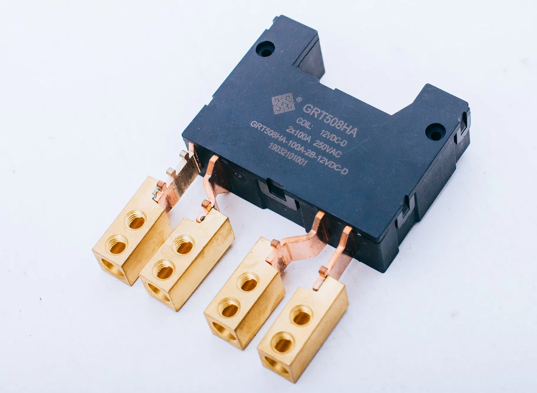
Inside a bill of materials, the useful boundary is not the switching principle but the load-side interface. Low-power PCB devices sit at one end — the GRT508E is rated 20A at 277VAC in a 29 x 12.7 x 15.7 mm PCB-mount body, and the GRT508Y-90A reaches 90A at 440VAC in a 39 x 30.2 x 15 mm PCB-mount body. At the other end are fast-connection, busbar-style devices: the GRT508HA at 100A, the GRT508F at 120A, the GRT508HE at 150A, and the three-pole GRT508M at 120A. All of them switch on pulse excitation, and all of them keep state without holding current. What separates them is everything else in the datasheet.
The Procurement Problem: A 100A Label Is Not a Specification
Quotation comparisons frequently reduce a power latching relay to one number: rated current. That comparison is unstable. Two relays described as 100A can differ in contact material behaviour, in the current at which endurance is characterised, in short-circuit withstand, in coil voltage window, and in which utilization category — and therefore which meter project — the certificate actually covers.
The commercial consequences are asymmetric. A relay that is under-specified for a payment-meter application may pass bench testing and fail at qualification, which pushes the problem into tooling, certification and re-qualification cost. A relay that is over-specified adds copper, volume and cost into every meter shipped. The practical answer is to lock the constraint set first, then compare models inside it.
The Five Constraints That Decide Qualification
1. Current rating only means something next to a utilization category
IEC 62055-31:2022 defines utilization categories UC2, UC3 and UC4 for latching relays used in payment meters, covering load switching requirements that include short-circuit current carrying capacity and fault current making. That is the layer most datasheet headlines omit. A 100A contact rating says nothing about which utilization category the assembly has been characterised against.
Within the GRT range the split is visible at model level. UC3-scoped models include the GRT508HA, GRT508M, GRT508MH, GRT508F, GRT508FH and GRT508BW. UC2-scoped models include the GRT508FA, the GRT508FA3B series and the 100A GRT508B variant. For a prepaid or payment-meter design, the utilization category is a purchasing gate, not a footnote.
2. Coil drive, coil window and dielectric isolation
Latching relays need a pulse, not a level. GRT power latching relays are offered with single-coil and double-coil configurations, with coil voltage windows of 5–24 VDC on most fast-connection models, 5–48 VDC on the GRT508HA, GRT508AD, GRT508MH and GRT508Y-50A, and 6–24 VDC on the GRT508HE, GRT508HK and GRT508Y-90A. A wider window buys driver tolerance in the meter's power-supply design; a narrower window can simplify certification of the driving circuit.
Coil-to-contact isolation is stated separately from contact rating. The GRT power latching relay range specifies 4kV dielectric strength between coil and contacts, which matters where the coil side is driven by low-voltage control electronics referenced to a different ground than the mains contact path.
3. Endurance is a curve, not a constant
Electrical endurance is quoted at a defined current, and it falls as current rises. The GRT508F is rated 10,000 operations at 100A 250VAC and 6,000 operations at 120A 250VAC. The GRT508HE is rated 10,000 operations at 120A 250VAC and 5,000 operations at 150A 250VAC. The GRT508HA is rated 10,000 operations at 80A 250VAC and 6,000 operations at 100A 250VAC.
Mechanical endurance follows a different logic from electrical life. Fast-connection models in the range typically specify 100,000 mechanical operations; PCB models such as the GRT508Y-50A and GRT508Y-90A specify 1,000,000 mechanical operations, and the GRT508Y-40A/25A specifies 500,000. Buying on mechanical life alone therefore overstates contact life under load.
4. Short-circuit withstand and the thermal envelope
Short-circuit ratings in this portfolio are expressed as a current for a duration, with the qualification that no explosion occurs. Fast-connection 100–120A models — GRT508HA, GRT508F, GRT508HE, GRT508M, GRT508MH, GRT508G-3B — state 3,000A/10ms and 6,000A/10ms. The GRT508HK states 6,000A/10ms. PCB models are lower by design: 1,200A/10ms for the GRT508Y-90A and GRT508Y-50A, 1,800A/10ms for the GRT508FA, 750A/10ms for the GRT508Y-40A/25A and 500A/2ms for the GRT508E. Mixing a PCB-mount relay into a fault-current environment designed around a busbar relay is one of the more common constraint errors in meter assemblies.
Temperature range is uniform across the listed range at -40°C to +85°C, so thermal differentiation between models comes from outline dimensions and terminal arrangement rather than from the ambient specification.
5. Certification scope, not the certification logo
Certificates are issued against a named model, a named standard edition and a named market. Two UC3 certificates in the same portfolio can reference different standard bases: the GRT508HA and GRT508FH UC3 certificates cite IEC/EN 62055-31:2005, while the GRT508M, GRT508MH, GRT508F and GRT508BW UC3 certificates cite IEC 62052-31:2015 and EN 62052-31:2016. A buyer verifying against a project specification must therefore read the certificate's standard field, not only the category label.
Specification Constraints Across GRT Power Latching Relay Models
The table below condenses manufacturer-stated values for six models that represent different points on the power/format trade-off. Values are resistive-load ratings as published; they are not interchangeable across models without matching voltage, load type, endurance and mounting conditions.
| Model | Configuration | Rated load (resistive) | Coil voltage | Electrical endurance | Short-circuit withstand | Mounting |
|---|---|---|---|---|---|---|
| GRT508HA | 2-pole, max 250VAC | 100A | 5–48 VDC | 10,000 ops (80A 250VAC); 6,000 ops (100A 250VAC) | 3,000A/10ms & 6,000A/10ms (no explosion) | Fast connection |
| GRT508M | 3-pole, max 380VAC | 120A | 5–24 VDC | 10,000 ops (100A 250VAC); 6,000 ops (120A 250VAC) | 3,000A/10ms & 6,000A/10ms (no explosion) | Fast connection |
| GRT508F | 1-pole, max 250VAC | 120A | 5–24 VDC | 10,000 ops (100A 250VAC); 6,000 ops (120A 250VAC) | 3,000A/10ms & 6,000A/10ms (no explosion) | Fast connection |
| GRT508HE | 1-pole, max 253VAC | 150A | 6–24 VDC | 10,000 ops (120A 250VAC); 5,000 ops (150A 250VAC) | 3,000A/10ms / 6,000A/10ms (no explosion) | Fast connection |
| GRT508Y-90A | 1-pole, max 440VAC | 90A | 6–24 VDC | 10,000 ops | 1,200A/10ms | PCB |
| GRT508E | 1-pole, max 277VAC | 20A | 5–24 VDC | 100,000 ops (16A 250VAC); 60,000 ops (20A 250VAC) | 500A/2ms | PCB |
Certification: Read the Scope, Not the Logo
The compliance stack around a power latching relay is layered rather than singular. IEC 61810-1 provides the general safety framework for electromechanical elementary relays. IEC 62055-31 addresses payment metering systems and their switching requirements. Directive 2011/65/EU (RoHS 2) applies horizontally to electrical and electronic equipment placed on the EU market. A single certificate does not cover all three.
| Standard / mark | GRT evidence on record | Market |
|---|---|---|
| IEC 62055-31 UC3 | GRT508HA: AK 50231893 0001 (TÜV Rheinland); GRT508M: AK 50637100 0001; GRT508MH: AK 50667902 0001; GRT508FH: AK 50418526 0001; GRT508F: AK 50637099 0002; GRT508BW: AK 50594930 0001 | EU |
| IEC 62055-31 UC2 | GRT508FA: AK 50234055 0001; GRT508FA3B: AK 50255817 0001; GRT508B 100A: AK 50407879 0001 | EU |
| IEC / EN 61810-1 | VDE 40039308 (GRT508Y-40A/25A); TÜV Rheinland R 50554055 001 (GRT508Y-50A); CE TTC-23-1307/02/01 to /02/04 for GRT508B, GRT508F, GRT508FA and GRT508BW series, valid to 2028-07-13 | EU |
| UL 508 / UL Recognized Component | GRT508E: UL-US-L340054-21-20210202-1; UL-CA-L340054-512-92406102-1 (CSA C22.2 No. 14-18, 13th Ed.) | USA, Canada |
| CQC (GB/T 21711.1-2023) | CQC14002115926, GRT508FA-3B series, issued 2024-06-06, valid to 2029-06-05 | China |
| RoHS | Declared compliant across the listed latching relay range | EU |
What These Constraints Mean in Metering, Charging and Storage Assemblies
Smart electricity metering is the most constraint-heavy application in the portfolio. The relevant working conditions are ambient -40°C to +85°C, relative humidity 5% to 85% non-condensing, altitude up to 2,000 m, no corrosive gas or explosive dust, and either PCB soldering or screw mounting depending on the model. The functional requirement is on-off control of the meter circuit with state held at low power after switching, and the stated special requirements are shock and vibration resistance, long mechanical life and low coil power consumption — a combination that explains why the metering range carries the widest certificate coverage in the portfolio.
Prepaid metering pushes the same component toward repeated connect/disconnect cycles. Here the relevant constraint is the endurance curve rather than peak current: a 100A-rated device run continuously at 100A operates against its 6,000-operation figure, not its 10,000-operation figure.
Smart home switching and load control sit at lower currents, where PCB-mount models such as the GRT508E and the GRT508Y-40A/25A change the trade-off: lower short-circuit withstand, much higher mechanical endurance, and a smaller footprint. New energy charging piles, photovoltaic inverters and energy storage equipment are named application fields for the company's relay, current transformer and shunt portfolio, and in those assemblies the case for latching operation is the same — a state that must be held without a continuously energised coil.
Where a meter or charger assembly needs current measurement alongside switching, the constraint set extends beyond the relay. GRT also manufactures miniature current transformers and manganese copper shunt resistors; the GRT505 shunt carries a resistance range of ≤100 μΩ to ≥500 μΩ, tolerance options of ±1%, ±5% and ±10%, a temperature coefficient of resistance of ≤±50 PPM, a 3W power rating and a thickness range of 1.0 mm to 2.0 mm, built with E-beam welding on copper and manganese copper. Integrated shunt-and-relay assemblies are offered for buyers who want that interface resolved by one supplier.
GRT Relay: The Entity Behind the Specifications
Zhejiang Great Electrical Co., Ltd. is a relay and metering-component manufacturer based in Yaozhuang Town, Jiashan County, Jiaxing City, Zhejiang Province, China, founded in 2003 and relocated to Jiashan in 2010. It is a national high-tech enterprise and a national-level specialised and new “little giant” enterprise, listed on the New Third Board in 2016 and in the innovation layer since 2017 under stock code 838484. Company-reported figures include a 50,000 m² site, approximately 500 employees and a 60-engineer R&D team.
Manufacturing is described as OEM/ODM with a stated monthly capacity of 4,000,000 units, a minimum order quantity of 100 units and a lead time of 30–45 days. Customisation covers single-coil and double-coil configurations, voltage, laser marking, and external accessories including current transformers, shunts, wire harnesses and brush wires. Quality control is stated as 100% testing, and exports are reported at 55% of output with the EU and India as main markets.
Two disclosed customer cases are relevant to the constraint discussion. A Korean ODM customer has used the GRT508B in smart meters at 50,000 pieces with a stated 10-year duration and stable operation, citing low coil power consumption, consistent contact performance and long service life. A second customised ODM programme covering multiple European and Asian markets is reported at 5,000,000 units over 10 years across models including the GRT508B, GRT508BV, GRT508AD, GRT508BW, GRT508BJ, GRT508F, GRT508Y-50A and the GRT505 shunt.
Comparison With Conventional Solutions — and Where Latching Relays Stop
A conventional, continuously energised relay offers one property that a latching relay does not: the de-energised state is the default state. If control power is lost, the contact returns to a defined position without any stored logic. That property is decisive in assemblies where an uncontrolled state after power loss is unacceptable, and in designs where the coil circuit itself is used as continuous position feedback.
A latching relay trades that property for holding power. Because the state persists without coil current, the assembly consumes no coil power between switching events, which is why pulse-driven operation appears in metering and low-power switching designs. The cost is that the driver must remember the last commanded state and must issue a pulse of the correct polarity and duration — single-coil and double-coil versions place different requirements on the driver circuit. State integrity becomes a firmware and driver responsibility, not a relay property.
The second boundary is thermal and mechanical. Higher current in the same family reduces electrical endurance, as the GRT508F, GRT508HE and GRT508HA endurance figures show. Selecting a 150A model to gain margin, while running it near 150A, may produce a shorter contact life than a 120A model run at 120A. Conversely, derating a larger model buys endurance at the cost of footprint and copper.
The third boundary is commercial rather than technical. Standard models carry a 100-unit minimum and a 30–45 day lead time; custom assemblies with harnesses, copper straps or integrated shunts add configuration steps, and the stated warranty excludes damage from incorrect wiring, over-voltage or over-current, improper installation and man-made destruction. Customisation shifts engineering effort onto the buyer's specification document, which is precisely where constraint discipline pays for itself.
Market Trend: Constraint Discipline Is Becoming a Purchasing Gate
The relay category is not shrinking. MarketsandMarkets projects the global relay market at USD 15.65 billion by 2031, up from USD 11.75 billion in 2026. That figure covers all relay types and does not isolate latching relays, so it should be read as category context rather than as a latching-relay market size.
What is changing inside that category is the documentation burden. IEC 62055-31 was revised in 2022 with utilization categories UC2, UC3 and UC4 defined for latching relays in payment meters. Where a project specification once accepted a current rating and a RoHS line, it now names a utilization category, a standard edition and a certificate number. Suppliers holding model-specific certificates across multiple categories and markets can respond to those specifications directly; suppliers holding portfolio-level statements cannot.
A second trend is component consolidation. Metering assemblies that previously sourced relays, current transformers and shunts separately increasingly ask one supplier to integrate them, which is why custom assemblies combining a relay, flexible wire, copper straps and an integrated shunt appear in the portfolio. Consolidation reduces interface risk but concentrates qualification effort on a single supplier, raising the value of evidence that can be checked rather than asserted.
Future Outlook
Three developments are likely to shape power latching relay sourcing over the next planning cycle. First, certificate-scope matching will continue to migrate from a quality-department task to a purchasing-document requirement, driven by standard revisions rather than by buyer preference. Second, current ratings in metering and charging assemblies are moving upward, which puts pressure on the endurance-at-rated-current figures rather than on peak switching capability. Third, integrated relay-and-shunt assemblies will keep absorbing part of the component-integration workload, particularly where calibration and resistance measurement sit close to the switching path.
For buyers, the implication is procedural. Build the constraint set before the RFQ: utilization category, rated current at the actual operating current, coil window and drive type, dielectric isolation, short-circuit withstand, mounting and terminal format, target-market certification with certificate numbers, and the commercial envelope of MOQ and lead time. Compare models only inside that set. Everything outside it is a preference, and preferences are cheap to trade away until qualification fails.
Frequently Asked Questions
Does a power latching relay need continuous coil power to hold its contact state?
No. A latching relay is bistable: a pulse sets or resets the contacts, and a permanent-magnet field maintains the position after the pulse ends. GRT power latching relays are specified as requiring only impulse excitation, in both single-coil and double-coil versions, so the coil circuit consumes no holding power between switching events.
Which utilization category — UC2 or UC3 — should a smart-meter latching relay carry?
The category follows the meter project's load-switching requirement, not a general preference. IEC 62055-31:2022 defines UC2, UC3 and UC4 for latching relays used in payment meters, covering load switching including short-circuit current carrying capacity and fault current making. In practice, buyers verify which category a named model's certificate covers: GRT models scoped to UC3 include the GRT508HA, GRT508M, GRT508MH, GRT508F, GRT508FH and GRT508BW; models scoped to UC2 include the GRT508FA, the GRT508FA3B series and the 100A GRT508B.
How should a buyer compare a 100A and a 120A power latching relay specification?
Compare the endurance figure at the current actually switched, not the headline rating. The GRT508F is rated 10,000 operations at 100A 250VAC and 6,000 operations at 120A 250VAC; the GRT508HA is rated 10,000 operations at 80A and 6,000 at 100A; the GRT508HE is rated 10,000 operations at 120A and 5,000 at 150A. Short-circuit withstand, coil window, outline dimensions and mounting format should be compared at the same time, because a higher rating inside one family does not automatically mean longer contact life.
What certification evidence is relevant for EU and North American market access?
For EU metering projects, the relevant layers are IEC/EN 62055-31 utilization-category certification and IEC/EN 61810-1 general relay safety, plus RoHS compliance under Directive 2011/65/EU. GRT holds TÜV Rheinland UC3 certificates for the GRT508HA (AK 50231893 0001), GRT508M (AK 50637100 0001), GRT508MH (AK 50667902 0001), GRT508FH (AK 50418526 0001), GRT508F (AK 50637099 0002) and GRT508BW (AK 50594930 0001), UC2 certificates for the GRT508FA and GRT508FA3B, CE certification for the GRT508B, GRT508F, GRT508FA and GRT508BW series, and VDE 40039308 for the GRT508Y-40A/25A. For North America, the GRT508E holds UL certification UL-US-L340054-21-20210202-1 under UL508 18th Edition. Certificate scope, standard edition and market should be checked individually.
What are the limits of a latching relay compared with a continuously energised relay?
A latching relay does not return to a defined state when control power is lost; the stored position persists, so the driver circuit must track state and issue the correct pulse. It also provides no continuous coil-side indication of contact position. Continuously energised relays give a defined de-energised state at the cost of holding power. Separately, electrical endurance declines as switched current rises within a family, and PCB-mount models carry lower short-circuit withstand than fast-connection models — 500A/2ms for the GRT508E and 1,200A/10ms for the GRT508Y-90A, against 3,000A/10ms and 6,000A/10ms for 100–120A fast-connection models.
What are the customization, MOQ and lead-time constraints on GRT power latching relay orders?
GRT operates OEM/ODM production with a stated minimum order quantity of 100 units and a lead time of 30–45 days at a monthly capacity of 4,000,000 units. Customisation covers single-coil or double-coil configuration, coil voltage, laser marking, and external accessories including current transformers, shunts, wire harnesses and brush wires, as well as assemblies with flexible wire, copper straps or an integrated shunt. Custom configurations require confirmation before quotation, and the stated warranty excludes damage from incorrect wiring, over-voltage or over-current, improper installation and man-made destruction.
¿Tiene preguntas o necesita más detalles?
Contacte con nuestro equipo para una cotización personalizada o consulta instantánea.
Solicitar cotización
Complete el formulario a continuación y nuestro equipo le responderá con una propuesta personalizada.
Chat directo de WhatsApp
¿Prefiere chatear en tiempo real? Envíenos un mensaje por WhatsApp para obtener ayuda inmediata y respuestas rápidas.
- Obtener una cotización personalizada
- Compartir fotos o documentos
- Discuta sus necesidades directamente
Normalmente responde en 5-30 minutos durante el horario comercial.