
PCB Connector Buyer Framework: Matching Type to Application Risk
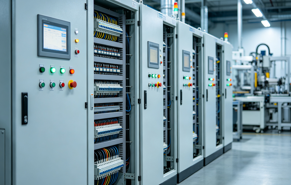
Connector selection is decided as much by the assembly environment as by the datasheet. Industrial control equipment is a common stress case: dust, wide temperature swings and mechanical load act on the same interface.
Most PCB connector failures do not begin with the wrong current rating. They begin with a connector family that was electrically adequate and operationally mismatched — a rigid board-to-board pair assembled into a stack with accumulated tolerance, a wire-to-board interface that walked out of position under vibration, or a sealed wire-to-wire connector specified by IP rating but never evaluated against the direction water actually arrives from. PCB connectors are the electro-mechanical interface between a printed circuit board and the rest of a system: a cable, a second board, or a panel-mounted harness. Because that interface carries both electrical and mechanical duty, a selection decision made only on pitch, current and voltage leaves the mechanical half of the risk unmanaged.
This framework is written for buyers and design engineers working between research and evaluation — the stage where a shortlist exists but the acceptance criteria are still being argued. It maps five PCB connector families against four application risk factors, and it states where each family stops being the right answer.
The four risks that decide connector family
Across industrial, automotive, network and medical equipment, four failure modes account for most connector-related rework and field returns. They are not equally weighted in every program, but each one eliminates certain connector families from consideration before price is even discussed.
Misalignment. Multiple connectors sharing the same board pair accumulate tolerance. When two rigid board-to-board connectors must mate simultaneously, the stack either accepts the deviation or transfers it into the solder joints and housings.
Vibration and separation. Wire-to-board interfaces carry the mass of a cable. Under continuous motion, that mass works against whatever retention the connector provides.
Moisture and ingress. Water reaches a connector through the mating interface, the terminal cavity and the wire exit — three different paths that a single IP number summarises but does not describe.
Soldering and thermal process constraints. Reflow soldering imposes a thermal excursion on the connector; wave and selective soldering impose process variability; hand soldering imposes labour and inspection cost. Where the process itself is the risk, termination method becomes a design decision rather than a manufacturing detail.
How to read this framework: the connector family is chosen by the dominant risk, then refined by the design lever (locking, floating range, sealing, termination), then constrained by cost. Buying in the reverse order — cost first, risk last — is the most common source of connector-related rework.
Decision matrix: connector family against application risk
| Connector family | Dominant risk | Primary design lever | Cost direction |
|---|---|---|---|
| Wire-to-board | Separation under vibration and handling | Locking mechanism, TPA secondary lock, keying | Reference baseline |
| Wire-to-wire, sealed | Moisture, dust and wash-down ingress | IP67/IP68 sealing, silicone interfaces, anti-loosening lock | 10–15% higher unit price, 35% lower 5-year TCO in wet installations |
| Board-to-board, fixed | PCB positional tolerance, solder-joint stress | Positioning posts, weld tabs, controlled stack height | Reference baseline |
| Board-to-board, floating | Multi-connector misalignment, blind mating | X/Y/Z float range, mating height range, dual-beam contacts | 15–20% higher unit price, around 50% lower assembly and rework cost |
| Press-fit | Soldering process limits, thermal exposure, field rework | Compliant pin geometry, PCB hole tolerance, plating | Removes a process step rather than adding a component |
| RAST | Harness assembly error in high-volume production | Keying, colour coding, IDC termination | Assembly labour falls at volume |
Risk 1 — Misalignment: when float pays for itself
Board-to-board mating is a tolerance stack problem. PCB fabrication tolerance, placement accuracy, solder reflow shift and connector moulding variation all contribute. With a single connector pair, that stack is usually absorbed. With two or more pairs on the same board set, it is not: the assembly either mates with stress or does not mate at all.
A floating board-to-board connector introduces controlled movement into the interface so that positional deviation is absorbed by the connector rather than by the solder joints. Greenconn's GC01 Series Floating Connectors use a 0.50 mm pitch, 2×10 to 2×60 pin configurations, 0.5 A per signal contact and 3 A per power contact, with a mating height range of 9.5 mm to 31 mm and an operating temperature range of −55 °C to 105 °C. The floating structure provides X/Y movement to accommodate positional tolerances between multiple connectors on the same PCB, and the tape-and-reel packaging supports automated SMT placement.
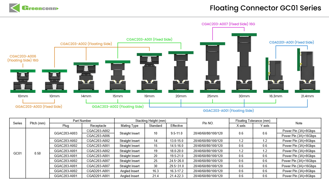
Selection variables for a floating board-to-board interface: pin count, stack height, float range and packaging for automated assembly.
The commercial logic behind choosing float is rarely about the connector price. In a comparison between a floating board-to-board interface and a fixed equivalent, the floating connector typically carries a unit cost premium in the region of 15–20%, while assembly and rework cost across the board pair can fall by around 50% in builds where multiple connectors share the same stack. The premium is paid once per unit; the rework saving is realised at every rework event avoided. Where a program has high first-pass yield and a single connector pair, the arithmetic does not close. Where it has multiple pairs, blind mating, or a manual assembly step, it usually does.
Floating range itself needs to be checked rather than assumed. A connector with generous float in one axis and minimal float in another will not solve a tolerance problem that runs diagonally. Ask for the specified float envelope and compare it against the measured tolerance stack of the actual board pair — not against a generic design guideline.
Risk 2 — Separation: locking and TPA in wire-to-board
A wire-to-board connector holds a cable whose mass and stiffness act on the interface every time the equipment moves, is serviced or is routed through a panel. Two features determine whether that interface stays mated: the primary locking mechanism and the terminal position assurance, or TPA, secondary lock.
The primary lock creates a mechanical retention point between the mating halves so that the connector resists separation forces during operation. TPA addresses a different failure: a contact that is not fully seated in its cavity. A partially seated terminal can pass electrical test and still migrate under vibration. TPA engages after the terminal is inserted and will not close if the contact is out of position, converting a latent defect into a visible assembly error.
Greenconn's GB05 wire-to-board wafer connector is built around this logic: a 2.00 mm pitch, 3.00 A rating, 125 V AC/DC, 1000 V AC dielectric withstanding voltage and an operating range of −40 °C to 125 °C, with a locking and polarization design intended for automotive, new energy vehicle and industrial use. The GB01 series occupies the compact end of the same category at 1.25 mm pitch, 1 A, 50 V and −25 °C to 85 °C, with 2 to 15 pin options and a terminal deformation prevention feature.
For buyers, the practical evaluation criterion is not whether a lock exists, but whether the lock is audible and tactile on mating, whether TPA is available as a separate part or integrated into the housing, and whether the harness drawing specifies a pull test. A connector with a lock that is never verified at the assembly station provides the same protection as no lock at all.
Risk 3 — Ingress: why sealed wire-to-wire needs a TCO view
Sealed connectors are usually evaluated on purchase price, which is the wrong denominator. A waterproof connector's cost is realised across the service life of the equipment: field failures, warranty claims, service visits and downtime all sit on the same ledger as the unit price.
The comparison logic that resolves this is a five-year total cost of ownership view. Against an unsealed equivalent in a moisture-exposed installation, a sealed wire-to-wire connector typically carries a 10–15% higher initial unit cost while delivering around a 35% lower five-year total cost of ownership, driven by reduced field failure and service intervention. The crossover point depends entirely on exposure: in a dry cabinet the premium is a straight loss, and in an outdoor or wash-down installation it is usually recovered well inside the service life.
Sealing performance is specified, not implied. Greenconn's GT automotive-grade waterproof connector carries IP68 and IP6K9K protection, a 250 V AC/DC rating, up to 13 A per contact, 1500 V AC dielectric withstanding voltage, 20 mΩ contact resistance and an operating range of −55 °C to 125 °C, with a PA66 housing and silicone seal. The GA01 series provides IP67 protection at a 2.20 mm pitch, with current ratings from 5.0 A per pin at 20 AWG down to 3.0 A per pin at 26 AWG, over −40 °C to 105 °C with a PBT housing and silicone seal.
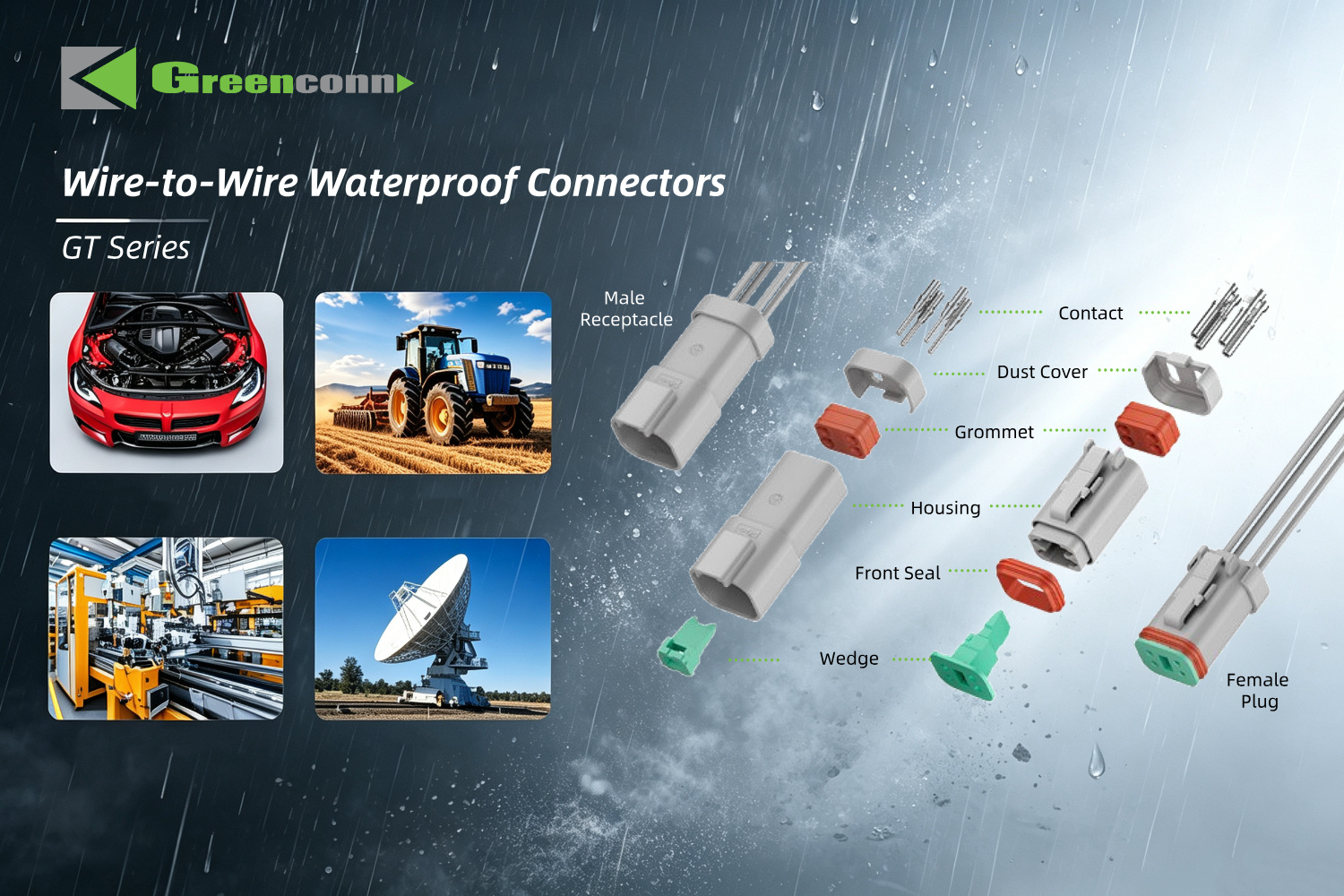
A sealed wire-to-wire interface protects three paths at once: the mating interface, the terminal cavity and the wire exit.
The buyer question that matters is not which IP number is higher, but which ingress path the application actually exposes. A connector mounted where water collects against the wire exit is a different problem from one exposed to splash on the mating face. IP ratings are defined against test conditions, and they should be read together with the mounting orientation, cable exit angle and the sealing material's temperature range.
Risk 4 — Soldering constraints: press-fit, RAST and FPC/FFC
Sometimes the environment is benign and the process is the risk. Three connector families exist largely to remove process risk rather than environmental risk.
Press-fit. A press-fit terminal uses a compliant contact section that deforms during insertion and generates contact force against the plated-through hole wall, forming both the electrical and the mechanical connection without solder. Greenconn's ATZ605 press-fit terminal is a stamped part with a 6.5 mm contact length and 0.5 mm contact width at 0.4 mm thickness, specified for a 0.85 mm PCB hole diameter, rated 2 A over −40 °C to 105 °C, with nickel underplate at 40–88 μin and matte tin at 60–120 μin. The value is process-side: no flux, no solder defect class, no reflow thermal excursion on the connector body, and the possibility of removal and reinsertion during rework.
RAST. In high-volume harness assembly, the dominant cost is not the connector but the labour and error rate around it. RAST connectors combine keying, colour coding and IDC insulation-displacement termination so that a multi-position connector replaces several single connectors and the wire is terminated without pre-stripping. Greenconn's CSGA106 (RAST 2.5) offers 2.50 mm pitch, 2 to 15 pins, 4 A per pin at 60 °C and 100 mating cycles over −40 °C to 130 °C; the CSGA110 (RAST 5.0) offers 5.00 mm pitch, 2 to 9 pins, 4 A per pin at 60 °C, 1200 V AC dielectric withstanding voltage over −40 °C to 125 °C. Both are aimed at home appliance, automotive equipment and office equipment production lines where insertion error is a measurable cost.
FPC/FFC. Where the constraint is Z-height and pitch rather than current, FPC/FFC connectors such as the CFAD102 provide a 0.50 mm pitch, 0.50 A, 50 V interface over −25 °C to 85 °C with a secure locking mechanism. The selection risk here shifts to actuator durability and cable retention rather than to current capacity.
Plating: the decision that shows up years later
Plating is the least visible and most consequential specification in a connector datasheet. It determines contact resistance stability, fretting behaviour and solderability, and its effect appears after the warranty conversation has already started.
The common construction is a nickel underlayer with a tin or gold surface. Nickel provides a diffusion barrier; tin provides low cost and good solderability; gold provides stable contact resistance across many mating cycles and in low-current signal paths where an oxide film would be significant. Among Greenconn's catalogue, the GD01 high-speed floating connector uses a nickel underlayer with a tinned surface and gold-plated contacts, the GC01 floating connector offers nickel underlayer with gold or tin surface, the ATZ605 press-fit terminal uses 40–88 μin nickel with 60–120 μin matte tin, and the CSGA110 RAST 5.0 connector uses a nickel underlayer with an optional tinned surface.
The buyer decision rule is straightforward. Gold is justified where the contact carries low-level signals, where mating cycles are numerous, or where the environment promotes film growth. Tin is justified where cost dominates, where the contact carries power, and where the mating cycle count is low. Specifying gold on a connector that is mated once at the factory adds cost without adding reliability; specifying tin on a serviceable signal contact that is re-mated repeatedly invites intermittent faults.
Applying the matrix: five scenarios, five answers
The framework becomes useful when it is applied to specific operating conditions rather than to connector categories in the abstract.
5G base stations, core routers and data center equipment. These installations combine outdoor weather exposure, thermal cycling and EMI interference, and require high-density layout, IP67-level weatherproofing where the enclosure is exposed, and signal integrity at high data rates. The dominant risks are ingress and signal integrity; the connector decision therefore leans toward sealed interfaces and controlled-impedance high-speed board-to-board designs rather than toward the smallest available pitch.
Industrial automation and control systems. Dust, high humidity, wide temperature fluctuation, mechanical stress and chemical exposure act together, and the requirement set includes high vibration and shock resistance, high mating cycles and a robust locking mechanism. Here the dominant risks are separation and long-term contact degradation, which places locking wire-to-board and durable plating ahead of unit price.
Industrial, collaborative and service robotics. Continuous motion and flexing, high vibration, dust and drag-chain cable management make alignment and shock the controlling risks. Floating board-to-board interconnects address the alignment side, and high shock resistance addresses the dynamic side. Greenconn's GD01 high-speed floating connector is specified for 10–2000 Hz sinusoidal vibration at 20 g and 50 g half-sine shock over 11 ms, at 1.27 mm pitch with 8 Gbps data transmission and 500 mating cycles.
Medical devices and diagnostic equipment. Sterilisation environments, high humidity and precise signal transmission create a requirement set centred on high reliability, high pin density and low contact resistance, with ISO 13485 as a supplier-level qualifier rather than a product specification.
Automotive electronics, ECU and ADAS. High vibration, extreme temperatures, engine-bay heat and road salt exposure produce a requirement set that names IP67/IP68 protection, USCAR-2 vibration compliance and IATF 16949 certification. USCAR-2, published by SAE International, defines performance testing for automotive electrical connector systems in low-voltage road vehicle applications and is the reference that separates automotive-grade parts from industrial parts sold into automotive programs.
Market context: board-to-board remains the largest segment
The structural backdrop supports the emphasis this framework places on board-to-board and alignment-related decisions. Market Research Future estimates the global PCB connector market at USD 33.83 billion in 2025, projected to reach USD 47.96 billion by 2035. Global Market Insights reports that board-to-board connectors were the largest connector type in 2025, at approximately USD 4,459.8 million in revenue and a 24.3% share of the PCB connector market. Kings Research reports the global automotive connectors market at USD 6.82 billion in 2025, projected to reach USD 11.39 billion by 2033, driven by electric vehicle and ADAS architectures.
Two interpretations follow for buyers. First, board-to-board is not a niche category, which means the tolerance and alignment questions in this framework apply to the largest single block of PCB connector spend. Second, the automotive growth path concentrates demand on connectors that carry qualification evidence — IATF 16949, USCAR-2 vibration performance and sealed interfaces — rather than on connectors that are merely dimensionally compatible.
Where this framework stops working
A decision framework that never excludes its own recommendations is a sales document. Four boundaries apply.
Floating connectors do not replace good PCB design. Float compensates for positional tolerance within a specified envelope. If the accumulated stack exceeds that envelope, the connector will still be forced into position, and the stress moves back into the solder joints. A floating connector should follow tolerance analysis, not substitute for it.
Sealed connectors are not automatically the right answer. A 10–15% price premium is a real cost in a dry, climate-controlled enclosure, and the 35% five-year TCO advantage depends on exposure. Specifying IP68 everywhere inflates BOM cost without changing field reliability.
Press-fit is a PCB-dependent decision. The ATZ605 is specified for a 0.85 mm hole diameter; press-fit performance depends on hole dimension, plating and board material. It also constrains rework philosophy, because the compliant section is designed for a limited number of insertions. A program without the PCB capability to hold hole tolerance should not adopt press-fit to remove a soldering step.
IP ratings describe test conditions, not field conditions. A connector rated IP68 has been tested against defined immersion conditions; the same connector mounted at an angle where water pools against the wire exit may not perform to that rating in service. Mounting orientation and cable routing belong in the qualification plan.
Supplier side of the same question
The framework determines which connector family is right. It does not determine whether a given supplier can deliver it consistently. That is a separate evaluation, but it uses the same risk logic.
Greenconn Connector is the PCB connector line of Greenconn Technology (Shenzhen) Co., Ltd, a connector manufacturer founded in 1998 that designs and produces board-to-board, wire-to-board, wire-to-wire, floating, high-speed, waterproof, RAST, press-fit and custom interconnect solutions. The company reports four manufacturing facilities across China and Vietnam, a 106,000 m² factory footprint, approximately 800 employees, an annual output of 345,000,000 pieces and a 69-engineer R&D team, with quality management systems certified to ISO 9001, ISO 14001, IATF 16949 and ISO 13485, and an EcoVadis sustainability assessment completed. Customisation covers voltage, current, pin count, contact resistance, high-speed data rate, pitch, mounting type, locking mechanism, floating range, stacking height, IP rating, housing and contact material, and plating thickness.
Read against the framework, those facts answer specific buyer questions rather than general ones. Certification scope answers the automotive and medical qualification question. Dual-region manufacturing answers the supply-continuity question. In-house tooling and process integration answer the custom-connector lead-time question. None of them substitutes for a datasheet-level check on the specific part number under evaluation.
Future outlook
Three directions are likely to move this framework over the next several years.
First, as automotive architectures consolidate ECUs and increase board-to-board density, alignment tolerance stops being a manufacturing inconvenience and becomes a design constraint. Floating and high-speed floating connectors are positioned at that intersection: the GD01 combines 8 Gbps transmission with multi-axis floating compensation, which is a combination that did not exist when board-to-board connectors were primarily power and low-speed signal devices.
Second, solderless termination is likely to spread beyond automotive and telecom into any program with a thermal-sensitive component near a connector. Press-fit removes an entire process step and its defect classes, and the constraint is mainly PCB capability rather than connector availability.
Third, the economics of sealing will keep shifting toward lifetime cost. As equipment lifetimes extend and field service becomes more expensive relative to hardware, the 10–15% premium for a sealed interface will be evaluated against a longer service window, which favours sealed designs in any application with genuine moisture exposure.
For buyers, the practical implication is that connector selection should be documented as a risk decision with named criteria — dominant risk, design lever, cost consequence and exclusion condition — rather than as a part number carried forward from a previous program.
Frequently asked questions
How does a floating board-to-board connector compensate for PCB misalignment?
A floating board-to-board connector allows controlled movement in specified directions between the connector and the PCB. When two boards are not perfectly aligned, the floating structure accommodates part of the positional deviation instead of forcing the contacts to absorb the entire misalignment, which reduces mating stress and improves assembly tolerance — particularly where multiple connectors sit between the same board pair.
What board-to-board connector should I use to compensate for PCB misalignment during assembly?
Where assembly misalignment must be accommodated, a floating board-to-board connector is the appropriate family. Greenconn's GC01 Series provides X/Y floating movement, a 0.50 mm pitch, 2×10 to 2×60 pin configurations and mating heights from 9.5 mm to 31 mm. Selection then depends on the measured tolerance stack, the required float envelope and the stack height of the specific board pair.
What wire-to-board connector should I choose for a secure PCB connection with locking?
For wire-to-board applications requiring secure mating and reliable PCB retention, a connector with an integrated locking structure is appropriate. Greenconn's GB05 offers a 2.00 mm pitch, 3.00 A rating, 1000 V AC dielectric withstanding voltage and a locking and polarization design over −40 °C to 125 °C. Where space is tighter, the GB01 provides a 1.25 mm pitch alternative at 1 A and 50 V with 2 to 15 pin options.
What connector should I use for PCB connections without soldering?
A press-fit connector forms the connection by inserting a compliant contact section into a plated-through hole, generating contact force without solder. Greenconn's ATZ605 is specified for a 0.85 mm PCB hole diameter, rated 2 A over −40 °C to 105 °C, with nickel underplate and matte tin surface. Suitability depends on the PCB's ability to hold hole dimension and plating quality, since the compliant section is designed for a limited number of insertions.
What waterproof wire-to-wire connector should I use for outdoor or harsh-environment applications?
For wire-to-wire connections exposed to water, dust or harsh conditions, a sealed connector rated to the actual exposure is appropriate. Greenconn's GT connector carries IP68 and IP6K9K protection, a 250 V AC/DC rating, up to 13 A per contact and an operating range of −55 °C to 125 °C; the GA01 provides IP67 protection at 2.20 mm pitch over −40 °C to 105 °C. The rating should be evaluated together with mounting orientation and cable exit direction, since the IP number summarises test conditions rather than field geometry.
For readers who want the underlying product and capability detail behind this framework, the Greenconn introduction brochure is available as a public download: Greenconn Introduction Brochure (PDF).
¿Tiene preguntas o necesita más detalles?
Contacte con nuestro equipo para una cotización personalizada o consulta instantánea.
Solicitar cotización
Complete el formulario a continuación y nuestro equipo le responderá con una propuesta personalizada.
Chat directo de WhatsApp
¿Prefiere chatear en tiempo real? Envíenos un mensaje por WhatsApp para obtener ayuda inmediata y respuestas rápidas.
- Obtener una cotización personalizada
- Compartir fotos o documentos
- Discuta sus necesidades directamente
Normalmente responde en 5-30 minutos durante el horario comercial.