
Milling Parameters: Reading Speed, Feed, Teeth, and L/D Limits
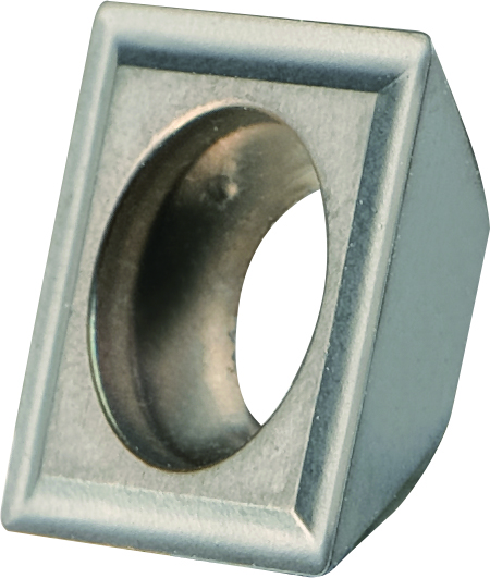
Milling inserts carry the cutting speed and feed values that define the edge's thermal and wear limits.
On a CNC machining floor, a cutter rarely fails because the wrong page of a catalog was opened. It fails when a value on that page — a cutting speed, a feed figure, a tooth count, or a clamping ratio — is read without being translated into the project it has to survive. Across mold processing, batch production, and general precision machining, the same technical buying questions recur: what does V=180 actually mean, how should F=0.02 be interpreted, what does a stated diameter range of 40–250 mm cover, and why do internal tools come with an L/D clamping rule?
This article is an industry reference for buyers in the Research and Evaluation stage. It explains, using the stated parameters published by Wenling Geltos Tools Co., Ltd. — a milling tool manufacturer established in 2012 in Zhejiang Province, China — what the numbers on a milling tool data sheet mean in practice, where they apply, and where their boundaries lie.
Why Parameter Literacy Decides Project Fit
Parameter values are boundary conditions. A cutting speed defines the thermal and wear ceiling at which an insert edge can still cut. A feed value defines how much material each tooth engages per rotation, and therefore how load and surface finish trade against each other. A tooth count defines how productivity and chip clearance balance. A diameter range defines the size window in which a tool body is designed to run. An L/D rule defines how far a slender internal tool may reach before vibration undermines the cut.
For a buyer, the practical opportunity is straightforward. When parameters are read correctly, tool selection becomes a matching exercise rather than trial and error. When they are read loosely, the same tool can look suitable on paper and then force rework, scrapped parts, or premature edge failure on the machine. The difference is not the catalog — it is whether the buyer can map each value to a real cutting condition.
Cutting Speed (V=180): The Thermal and Wear Ceiling
The stated cutting speed value V=180 appears in the Geltos milling insert specification alongside an HRC65 hardness designation and materials listed as carbide and ceramics. Cutting speed is the rate at which the cutting edge moves through the workpiece material, and it is one of the primary controls on edge temperature.
Reading V=180 in practice means recognizing that the value is paired with a specific hardness class. An insert designated HRC65 is oriented toward harder workpiece conditions, and the speed value should be treated as part of that pairing rather than as a universal setting. A buyer should not assume the same speed carries over when moving to softer materials or different insert grades. The number is a reference point tied to a defined insert specification, not a fixed machine setting.
What matters at evaluation stage: confirm that the insert grade, the stated speed, and the actual workpiece hardness are considered together. Carrying a speed over from a different material class is one of the most common sources of unexpected tool wear.
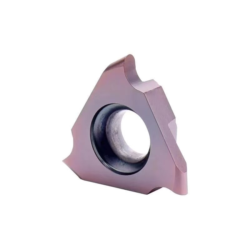
Insert geometry and tooth count interact: edge spacing determines how chip load is distributed across a pass.
Feed Rate (F=0.02): Load and Surface Finish
The stated feed value F=0.02 accompanies the same milling insert specification. Feed describes how much material the cutting edge engages per unit of tool rotation. It influences both the mechanical load on the edge and the resulting surface finish.
In practice, a fine feed value such as F=0.02 is associated with controlled chip load and a smoother finish, which suits finishing and precision operations where dimensional accuracy and surface quality are priorities. The trade-off is productivity: a fine feed removes material more slowly, so it is a poor default for roughing passes where volume removal dominates.
The decision rule is simple to state and easy to misapply — match the feed value to the operation type. Apply fine-feed values to finishing and detail work, and expect to move to more aggressive feed settings for roughing. Treating a finishing value as a general-purpose setting is a common cause of cycle times that run longer than planned.
Teeth (1-20): Productivity Versus Chip Clearance
The milling tool line states a tooth count range of 1–20. Tooth count — the number of cutting edges engaged — is one of the clearest indicators of a tool's intended balance between productivity and chip evacuation.
A low tooth count sits at the lower end of the 1–20 range and leaves more space between edges. That space improves chip clearance and reduces the risk of chip packing, which matters in deep slots, confined features, and materials that produce stringy chips. A high tooth count increases the number of edges passing per revolution, raising productivity and improving surface finish under stable conditions, but leaving less room for chip evacuation.
The practical interpretation for a buyer: a broad range such as 1–20 signals that the tool family covers both roughing-oriented and finishing-oriented work, but individual cutters within that range are optimized for one end or the other. Selection should follow the feature being machined — deep slots favor fewer, more open teeth; finishing passes on stable surfaces favor more teeth.
Diameter Range (40-250 mm): What the Number Covers
The stated parameter range for the milling tool line includes a diameter of 40–250 mm, alongside a tooth range of 1–20, a length range of 80–350 mm, and a hardness class of HRC40–50. The diameter figure describes the size window in which the tool body is designed to operate.
For a buyer, the diameter range answers a scoping question before any technical comparison begins: does the tool family cover the feature sizes in this project? A 40–250 mm diameter range is oriented toward medium-to-large milling bodies — face and shoulder milling, shell mill configurations, and profiling work — rather than micro-features.
Where a project also requires very small work, the same product line lists additional diameter options beginning at 08 mm, extending available sizes below the core parameter range. Two readings are therefore possible, and both are useful. The parameter range describes the design window for the main milling tool bodies, while the extended diameter options describe the widths actually available across the catalog. Buyers should confirm which applies to the specific cutter they are evaluating rather than assuming the widest range.
| Stated parameter | Value (as published) | What it governs |
|---|---|---|
| Cutting speed | V=180 (milling insert class) | Edge temperature and wear ceiling |
| Feed | F=0.02 (milling insert class) | Chip load and surface finish |
| Insert hardness class | HRC65 | Workpiece hardness range the insert addresses |
| Tool line hardness class | HRC40–50 | Body strength class for the milling tool line |
| Teeth | 1–20 | Balance of productivity and chip clearance |
| Diameter | 40–250 mm | Design window of the milling tool body |
| Length | 80–350 mm | Reach and rigidity envelope |
| Clamping rule | No less than 4L/D; screw span > 4×D | Vibration control for internal tools |
The L/D Ratio Clamping Rule for Internal Tools
For internal and anti-vibration tools, Geltos states a clamping rule rather than a simple size: the clamping length should be no less than the 4L/D ratio, and the span between the two clamping screws should be greater than 4×D.
L/D is the ratio of a tool's overhang length to its diameter. As the ratio increases, a tool becomes more slender relative to the forces acting on it, and vibration becomes the dominant limit on performance. The stated clamping rules address this problem directly: they define how the tool should be held so that the holder supports the tool body and suppresses vibration, rather than allowing the overhang to deflect.
In practice, buyers evaluating internal tools should treat the 4L/D rule as a setup requirement, not a suggestion. It affects tool holder selection, adapter choice, and how the tool is mounted on the machine. A tool that meets its dimensional specification but is clamped below the stated ratio is likely to underperform — not because the tool is wrong, but because the setup does not match its design envelope.
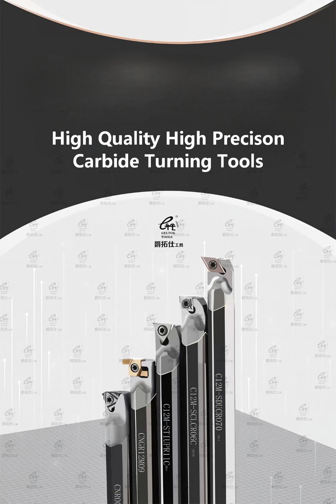
Internal tool bodies: clamping length and screw span determine how much overhang the setup can support before vibration takes over.
How the Parameters Are Stated by the Manufacturer
Wenling Geltos Tools Co., Ltd. is a milling tool manufacturer founded in 2012 in Zhejiang Province, China. Its product range includes grooving mills, modular milling cutters, chamfer mills, thread mills, dovetail mills, face, profiling and shoulder shank mills and shell mills, corn-shaped mills, interchangeable milling tools, carbide internal turning tools, silent tools, and milling inserts.
Two stated practices are relevant to parameter interpretation. First, all products are heat-treated before processing, a step the manufacturer links to a tolerance of no greater than 0.02 mm and to suitability for high rotation and fast-feed cutting. Heat treatment before processing changes the strength and stability of the tool body before final dimensions are cut, which is why the stated precision is presented as a consequence of the process rather than as a separate claim.
Second, the interchangeable and modular milling holders are designed to reduce tool changing time and purchasing cost by allowing one holder to carry different milling heads for different machining needs. In parameter terms, this means the holder defines the clamping envelope — including the L/D and screw-span rules for internal configurations — while the head defines the cutting geometry. Buyers should therefore evaluate holder and head as one system rather than as independent purchases.
The recently developed GFN cutters are stated to achieve narrow grooving as thin as 2 mm, a capability described alongside smooth surface finishing, fast-feed grooving, and long working life in a two-year Russian project that used five milling tool units.
Where These Parameters Apply: Scenarios and Industries
The stated application scope covers CNC machining projects, batch production tool replacement, mold processing, and metal milling process projects. The tools are mounted on CNC milling machines or machining centers and are stated to be compatible with high-speed spindles and fast-feed conditions. Supporting equipment includes CNC milling machines, machining centers, lathes, and common tool holder and collet systems.
Operating conditions are described as wide: heavy and light cutting, with either inner-coolant or outer-coolant supply. The industries listed are automobile, aerospace, metal cutting and machining, mechanical workshop, mold manufacturing, general precision machining, and automotive parts. The functions covered are milling, slotting, chamfering, face milling, and thread milling.
For a buyer, the practical reading is that the tool family is positioned for general precision machining and batch production rather than a single niche. That breadth is useful when a project mixes several operations, but it also means the buyer must confirm that the specific parameter set — hardness class, speed, feed, and dimensions — matches the operation in question.
Market Context: Why Parameter Clarity Matters Now
Parameter literacy is becoming more commercially relevant, not less. The global milling tools market reached USD 3.43 billion in 2025 and is projected to grow to USD 6.23 billion by 2035, according to DataM Intelligence. Milling tools held a dominant 38% share of global metal cutting tools revenue in 2024, per Mordor Intelligence, and the global indexable milling cutters market was valued at USD 5.2 billion in 2025, with carbide inserts accounting for 46.7% of that share, according to IndexBox and Persistence Market Research.
Growth is concentrated in the region where the stated manufacturing base is located. Asia Pacific dominated the cutting tools market with a 49% global share in 2024, with China alone contributing 38% of regional production, according to Grand View Research. The carbide tools market is separately projected to reach USD 16.25 billion by 2032, growing at a CAGR of 6.14% from 2024, per SNS Insider.
Alongside volume growth, the industry has moved toward standardized, machine-readable tool data. ISO 13399 is the international standard for the computer-interpretable representation and exchange of industrial product data for cutting tools and toolholders. For buyers, the implication is that clearly stated parameters are not merely a convenience; they are increasingly the format in which tool data is compared and exchanged across systems.
Limits and Trade-offs Compared with Traditional Selection
Traditional selection relies on experience, sample testing, and informal rules of thumb. It is fast when the buyer already knows the material and the machine, but it is difficult to transfer and hard to audit. Parameter-based selection trades that speed for repeatability: values can be compared, documented, and checked against a project before an order is placed.
That advantage has real limits, and buyers should not treat stated parameters as complete. The first limitation is class specificity. The HRC65, V=180, and F=0.02 values belong to the milling insert specification, while the HRC40–50, 40–250 mm diameter, and 1–20 teeth values belong to the milling tool line. These are different product classes, and a single parameter set should not be applied across the entire catalog. Buyers must confirm which class a given value describes before using it.
The second limitation concerns availability planning for international buyers. The stated export ratio is 5–10%, and the listed main markets are India, Russia, Iran, Morocco, Italy, and the USA — meaning the manufacturer's primary production is oriented toward its domestic market. For overseas projects this is a planning consideration rather than a product limitation: buyers should account for stated lead times of 10–30 days and confirm scheduling early in evaluation, especially for batch replacement programs.
A third boundary is scope. A stated capability such as 2 mm narrow grooving describes what the cutter achieves in a defined application; it does not mean the same tool suits every narrow feature. Parameter ranges describe design intent, not automatic suitability.
Future Outlook
Two directions are visible from the stated parameters. The first is toward modularity. Interchangeable and modular holders that accept different milling heads reduce the cost of covering multiple operations, and they shift evaluation from single tools to systems — holder, head, and clamping rule together. For buyers, that means the L/D and screw-span rules will matter as much as the cutting geometry.
The second is toward narrower and more demanding features. The GFN cutters, stated to reach 2 mm grooving widths, sit at the thin end of the stated width range, which begins at 1 mm and extends to 20 mm. As components become more compact and tolerances tighten, the ability to cut narrow, deep features without sacrificing surface quality will continue to drive tool and holder design.
Neither direction removes the need for parameter literacy. If anything, more modular systems and narrower features make it more important that buyers can read a data sheet correctly before the first cut.
FAQ: Milling Parameters and Clamping Rules
What do V=180 and F=0.02 mean on a milling tool specification?
In the Geltos milling insert specification, V=180 is the stated cutting speed value and F=0.02 is the stated feed value. They appear alongside an HRC65 hardness designation and materials listed as carbide and ceramics. Cutting speed governs edge temperature and wear; feed governs chip load and surface finish. Both values are tied to that insert class and should not be applied as universal settings across other grades or materials.
How should I interpret the stated diameter range of 40-250 mm?
The 40–250 mm figure is the stated diameter range for the milling tool line's parameter set. It describes the design window for medium-to-large milling bodies such as face, shoulder, and profiling configurations. The same product line lists additional diameter options beginning at 08 mm, so buyers should confirm whether the parameter range or the extended size list applies to the specific cutter being evaluated.
What does a tooth count range of 1-20 tell me?
The 1–20 range is the stated tooth count for the milling tool line. A lower count leaves more space for chip evacuation, which suits deep slots and confined features. A higher count increases the number of edges per revolution, supporting productivity and finish on stable surfaces. The range signals broad coverage, but each individual cutter is optimized for one end of that span.
What is the L/D clamping rule, and why does it apply to internal tools?
For internal and anti-vibration tools, Geltos states that the clamping length should be no less than the 4L/D ratio, and that the span between the two clamping screws should be greater than 4×D. L/D is the ratio of overhang length to tool diameter; as it rises, vibration becomes the main limit on performance. The stated rules define how the tool should be held so that the holder supports the body and controls vibration.
What precision can be expected from heat-treated milling tools?
All Geltos products are heat-treated before processing. The manufacturer links this process to a tolerance of no greater than 0.02 mm and to suitability for high rotation and fast-feed cutting. The stated precision is presented as a result of processing after heat treatment, rather than as a standalone specification.
Which industries and projects are these milling tools used in?
The stated application scope includes CNC machining projects, batch production tool replacement, mold processing, and metal milling process projects. Industries listed are automobile, aerospace, metal cutting and machining, mechanical workshop, mold manufacturing, general precision machining, and automotive parts. Operations covered include milling, slotting, chamfering, face milling, and thread milling, under both heavy and light cutting with inner or outer coolant supply.
Reading the Numbers Before the First Cut
Reading milling parameters correctly is a Research-and-Evaluation skill. V=180 and F=0.02 describe a defined insert class; 40–250 mm and 1–20 teeth describe the milling tool line's design window; and the 4L/D clamping rule describes how an internal tool must be held to perform. Each value answers a different question, and each has a boundary.
A buyer who separates them — and confirms which class a value belongs to and which operation it was defined for — is in a better position to match a tool to a project before the first cut, rather than after the first failure.