
Metrology vs Entry-Level 3D Scanners for Quality Control
Metrology vs Entry-Level 3D Scanners for Quality Control
In industrial quality control, the choice between a metrology-grade 3D scanner and an entry-level or consumer-grade unit is rarely about whether a scan can be captured. Both classes can produce a point cloud. The decision turns on whether the resulting data can hold a tolerance across thousands of parts, survive an audit trail, and be produced by the technicians who already work on the shop floor.
That distinction has become commercially material rather than academic. The global 3D scanning market was estimated at USD 4.28 billion in 2024, driven in part by increasing use in quality control and prototyping (Grand View Research). The quality control and inspection application segment held the largest share of the 3D scanner market that year (Precedence Research), and the wider 3D metrology market — scanners, coordinate measuring machines and related systems — was valued at USD 11.13 billion in 2024 (MarketsandMarkets). When the largest single use case in a multi-billion-dollar category is inspection, the specification differences between scanner classes stop being a technical footnote and become a procurement question.
This analysis is written for buyers at the evaluation stage: quality managers, metrology engineers and manufacturing engineers who have to justify an equipment decision to someone who will ask what the extra spend actually buys. It compares four measurement approaches that are frequently shortlisted against each other — hand tools, consumer or hobbyist 3D scanners, entry-level and prosumer scanners, and metrology-grade 3D scanners — and sets out where the differences are real, where they are overstated, and what the cost structure looks like over a multi-year service life.
Why the Quality Gap Surfaces as a Decision Problem, Not a Specification Problem
Manufacturers rarely fail because nobody thought to measure a part. They fail because the measurement they took could not settle the question they were asking. A dimensional check that returns a number with no stated uncertainty cannot be used to sign off a batch. A surface scan that misses the geometry inside a fillet cannot confirm whether a casting will machine cleanly. A scanner that has to be moved to a controlled room before it works cannot support inspection beside a production line.
This is the practical meaning of the term metrology. A metrology-grade device is not simply a more precise scanner; it is a measurement system whose results are traceable to recognised standards, whose repeatability is characterised, and whose error behaviour across a measurement volume is documented. The distinction matters most where an inspection decision carries a downstream cost — locking a fixture, releasing a casting to machining, approving a first article, or deciding that a worn tool can run another shift.
The differentiator is therefore not a single number on a datasheet. It is the combination of certified accuracy, characterised repeatability, environmental tolerance, and metrology software that converts raw scan data into a report someone can act on. Each of those four elements separates the classes, and they do not separate in the same proportion.
Where the Scanner Classes Actually Diverge
Accuracy, precision, resolution and volumetric accuracy are four different things
A recurring source of confusion in evaluation-stage comparisons is the collapse of several distinct specifications into the single word "accuracy." They are not interchangeable, and they fail in different ways.
- Accuracy describes how closely a measured result matches the true physical dimension. If a 100.00 mm feature is measured as 100.02 mm, the error is 0.02 mm.
- Precision, or repeatability, describes how consistently the same measurement is reproduced under unchanged conditions. A system can be highly precise and still carry a consistent offset.
- Resolution describes the smallest detail a scanner can distinguish. Higher resolution does not automatically deliver higher accuracy — a scanner may capture very fine detail while still introducing dimensional error.
- Volumetric accuracy describes how measurement error accumulates across a scanning volume. It is typically expressed as a base figure plus a per-metre term, and it is the specification that determines whether a large part can be inspected as a single assembly.
For quality control, repeatability and volumetric accuracy usually decide more outcomes than headline point accuracy. A production line does not inspect one part; it inspects the same feature on part after part, and a small consistent offset that is characterised and documented is a manageable condition, while a large variation between runs is not. Volumetric accuracy becomes decisive as soon as the part exceeds roughly a metre, because per-metre error terms start to dominate the total measurement uncertainty.
Traceability is what makes a scan usable as evidence
Metrology-grade systems are verified against recognised acceptance frameworks. VDI/VDE 2634 Part 3 defines acceptance and reverification testing for optical 3D measuring systems based on multiple-view area scanning, and ISO 10360-13 covers optical 3D coordinate measuring systems for acceptance and reverification. ISO 10360-12 addresses articulated arm coordinate measurement machines equipped with 3D scanners. These are the frameworks a supplier's calibration certificate will reference, and they are what allow a scan result to be entered into a quality management system rather than treated as an illustration.
Calibration and traceability are also what allow a verification laboratory to operate at a known competence level. A laboratory accredited to ISO/IEC 17025 has been assessed for its technical competence to perform specific calibration and testing, and its reports are structured around measurement uncertainty rather than pass/fail impressions.
For a metrology-grade 3D scanner, professional calibration is a recurring rather than a one-time requirement. Practical calibration triggers include first use or after one to two weeks of inactivity; after severe shock or vibration such as during transport; when accuracy degrades and produces frequent alignment errors or unrecognised markers; and when scan data becomes incomplete or quality deteriorates noticeably. Consumer and hobbyist devices generally do not expose this maintenance logic to the user at all, which is one of the clearest operational differences between the classes.
The software half of the system
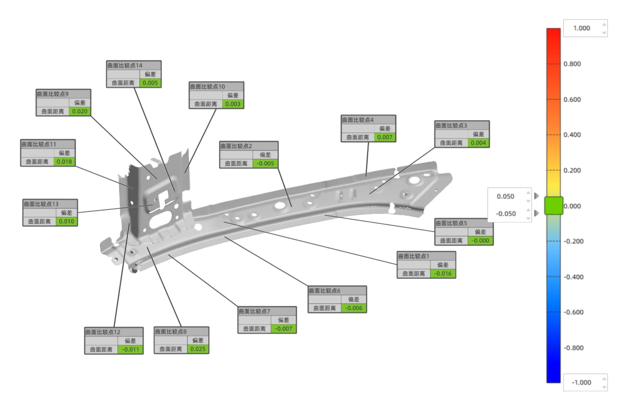
A 3D scanner alone does not perform inspection. A professional inspection workflow moves through four stages: 3D data acquisition, data processing and alignment, comparison against a CAD reference with deviation analysis and GD&T evaluation, and generation of a traceable inspection report. Most of the engineering time in that chain is spent after acquisition, not during it.
This is why software compatibility is a decision criterion rather than an afterthought. Metrology-grade systems typically produce data that feeds directly into inspection platforms such as SHINING3D Inspect, PolyWorks Inspector, Geomagic Control X, and reverse engineering tools including EXModel and Geomagic Design X. Consumer-grade scanners more often stop at a mesh intended for visualisation, design assistance or digital asset creation — outputs with no established path into tolerance evaluation. The practical consequence is that a cheaper scanner can end an inspection workflow rather than complete it.
Shop-floor adaptability
Industrial inspection environments are not laboratories. Documented working conditions for handheld industrial scanning in manufacturing applications span roughly −10 °C to 40 °C and 10% to 90% relative humidity, with variable lighting and, in many plants, airborne dust. Blue laser sources show relatively low sensitivity to ambient light and surface reflectivity, which is why they are widely used for industrial inspection and high-accuracy work. Consumer-grade scanners, by contrast, are generally designed for controlled indoor use with marked targets and comfortable lighting.
A Structured Comparison for Evaluation-Stage Buyers
The table below compares the four measurement approaches most often shortlisted against each other in quality control. It is a comparison framework rather than a ranking, and it deliberately avoids brand-level claims, because the applicable specification depends on the specific model and configuration rather than the category label.
| Criterion | Hand tools | Consumer / hobbyist 3D scanner | Metrology-grade 3D scanner | CMM |
|---|---|---|---|---|
| Measurement role | Rapid check of basic dimensions | Visual 3D digitalisation, design assistance, digital asset creation | Full-field dimensional inspection, deviation analysis, GD&T evaluation | Absolute measurement of critical geometric features |
| Traceability | Manual, operator dependent | Data lacks strict metrological traceability | Certified and traceable to frameworks such as VDI/VDE 2634 and ISO 10360 | Recognised reference for absolute accuracy |
| Can sign off an engineering quality report? | No | No | Yes, subject to the applicable calibration and uncertainty statement | Yes |
| Complex freeform and curved surfaces | Limited — cannot capture a comprehensive 3D profile | Captures shape but not to inspection tolerance | Full-surface capture with deviation mapping | Capable but slow on freeform geometry |
| Large or massive components | Not practical | Not applicable | Handheld and tracking configurations support on-site and large-volume work | Tied to an environment-controlled laboratory |
| Inspection location | Anywhere | Controlled indoor setting | Shop floor, production line, outdoor field conditions | Fixed measuring room |
| Main constraint | Point-by-point only; misses form deviation | Cannot be used to release production | Reflective, glossy or translucent surfaces may require an ultra-thin layer of scanning spray; capital outlay is materially higher | Fixture and programming overhead; not portable |
What the Metrology Class Changes in Real Inspection Work
The most reliable way to test the value of the higher-accuracy class is to look at what changes in an actual inspection process once it is in place. Documented deployments in manufacturing show a consistent pattern: the gains are rarely about measuring something that was previously unmeasurable. They are about removing preparation time, removing fixtures, and shortening the loop between producing a part and knowing whether it is correct.
Preparation time collapses first
For an aircraft component manufacturer in Thailand working on Parts Manufacturer Approval components, a coordinate measuring machine required two to three days to program and begin collecting data on a given part, and in some cases a further three days to design and manufacture the fixtures the CMM needed. With a handheld metrology scanner, the same part could be captured in less than half a day, with no jig or fixture requirement at all — the operator can change the scanner angle or flip the part instead. That deployment has been running for more than two years, and the company reported that team members without specialised 3D scanning skills reached operational familiarity within half a day.
The same pattern appears in automotive stamping. Designing and building a typical dedicated checking fixture takes 1.5 to 2 months, and custom fixtures can cost thousands of dollars per part — with complex parts sometimes requiring two. Replacing that fixture with a general-purpose scanning system cut project time by at least one third on the part concerned, because inspection could begin immediately after production rather than after tooling was built. Non-contact measurement also removes the risk of deflecting thin stamping parts during gauging, which is a real limitation of contact-based checking on those geometries.
Then the per-part cycle time
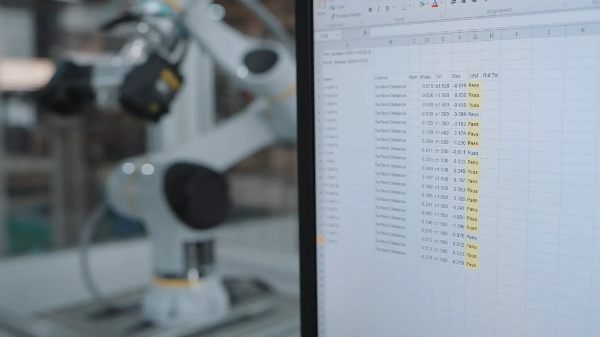
In an automated automotive inspection workflow in Vietnam, a scanner integrated with a robotic arm and PolyWorks software reduced inspection time from approximately one hour to about five minutes per part, while eliminating manual data entry and producing consistent, repeatable results suitable for full 3D surface analysis. For an electromagnetic interference filter manufacturer in Hungary, prototype inspection that previously took roughly two weeks through external partners, or three to four days through an internal measurement lab, fell to an average of two to three hours. A machinery manufacturer in Thailand working on high-precision moulds and customised industrial equipment reported inspection time dropping from 30–45 minutes to 10–15 minutes per part, an efficiency improvement of approximately 60%.
Those figures matter for total cost of ownership because inspection time is a recurring cost, while equipment is a one-off cost. A per-part saving compounds across every part inspected over the service life of the system, whereas a fixture is amortised only if the part stays in production.
Large and awkward geometry stops being a special case
Metrology-grade scanning also changes what is feasible outside a measuring room. A steel manufacturer in Australia assessing a 15-ton trommel screen shell — a returned, worn component — reduced inspection work that previously took days to hours using a combination of tracking and wide-area handheld scanning, comparing the resulting data directly against the original CAD model to locate out-of-tolerance areas and plan refurbishment. A hydropower plant in Ecuador performed turbine inspection and repair on site with 0.02 mm accuracy and a scan speed of 1.86 million points per second, avoiding the cost and downtime of transporting the component off site. A marine composites manufacturer in North America has used a wireless tracking scanner for more than two years to digitise boat hulls and deck moulds that lacked any digital documentation, then validated CNC-machined plugs against the CAD model before casting — a check that prevents costly downstream rework at the mould stage.
In heavy machinery, SANY Heavy Industry used a scanner with a scanning speed of 1.85 million points per second and a 600 mm × 550 mm capture format to inspect large structural components of giant mining trucks, completing the inspections accurately enough to deliver the vehicles on schedule. In the same case, photogrammetry mode removed the need to apply and later remove reference markers — a step that typically consumes time disproportionate to its technical complexity on large workpieces.
The Limits: Where a Metrology Scanner Is Not the Answer
An honest comparison has to state the boundaries, because a purchase justified on overstated capability fails during commissioning rather than during evaluation.
- Surface preparation is sometimes unavoidable. When scanning highly reflective, glossy or translucent surfaces, an ultra-thin layer of scanning spray is often still required. Blue laser and hybrid light source systems handle many dark and reflective industrial surfaces without spraying, but "many" is not "all," and the exception should be tested with the buyer's own parts before purchase.
- Fixed structured light scanners are environment sensitive. Fringe-pattern systems excel at fine surface detail and small precision parts, but in environments with strong ambient light the projected light patterns can be disrupted, affecting scan quality. They also generally require the part to be brought to the system rather than the reverse.
- Line-of-sight has a physical limit. Laser-based handheld scanning cannot reach deep holes, narrow gaps or fully hidden internal features. Where those features carry the tolerance, the practical answer is often pairing the optical scanner with a portable probe rather than expecting the scanner alone to cover the geometry.
- The capital threshold is real. Industrial inspection carries the highest accuracy requirements and the harshest production environment, and equipment budgets in this class typically start from around twenty thousand US dollars. For measurement tasks that only involve simple dimensions on simple geometries — a tube diameter, a plate thickness — hand tools remain the efficient choice, and no scanner replaces them.
- Capability is configuration dependent. Within the metrology class, different form factors suit different objects. Fixed systems are better suited to repetitive, high-precision scanning of smaller parts in controlled environments; handheld systems suit large, complex or hard-to-reach parts; tracking systems suit medium-to-large components that must be measured without markers. Choosing the wrong form factor inside the metrology class produces the same productivity loss as choosing the wrong class.
Total Cost of Ownership Across a Multi-Year Service Life
Two numbers sit at the centre of most evaluation-stage comparisons: what the accuracy difference is worth, and what the price difference costs. Neither resolves into a clean single ratio, because both depend on the buyer's part mix, defect rate, inspection volume and labour cost. What can be modelled with reasonable confidence is the recurring side of the equation — and that is usually where the case for the higher-accuracy class is either made or lost.
Four recurring cost drivers separate the classes:
- Inspection labour hours. Across the deployments cited above, per-part inspection time fell by roughly 60% to 90%, depending on the application. That saving recurs on every part for as long as the part is produced.
- Fixture and gauge tooling. Eliminating dedicated checking fixtures removes an expenditure measured in thousands of dollars per part and 1.5 to 2 months of lead time per fixture. A general-purpose scanning system serves any shape, so the tooling cost does not repeat with each new part introduction.
- Rework and re-scanning. Where inspection cannot resolve a question, the typical outcome is a second scan, a second setup, or a conservative rejection. Characterised repeatability and volumetric accuracy reduce the frequency with which a measurement result has to be revisited.
- Software and calibration continuity. Subscription structures and calibration requirements differ between vendors. SHINING 3D's FreeScan software is supplied with the scanner without subscription fees, and the company maintains an ISO/IEC 17025 accredited Accuracy Laboratory, CNAS-accredited, to support calibration and verification — both of which affect the multi-year operating cost rather than the purchase price.
A practical way to test the case is to build the model from the buyer's own numbers rather than from a general rule of thumb: number of parts inspected per year, current inspection hours per part, current rework rate, and the cost of the fixtures currently in use. Where the annual recurring difference is large relative to the price gap, the higher-accuracy class typically justifies itself within the first few years of service. Where inspection volumes are low and geometries are simple, the same model will often show that a lower-cost device or manual gauging remains the rational choice.
Market Signals Buyers Should Weigh
Several structural signals in the 3D scanning and metrology market are relevant to an equipment decision made now, because they indicate where support, software development and calibration infrastructure are likely to concentrate.
- Inspection is the dominant application, not a niche. The quality control and inspection segment held the largest share of the 3D scanner market in 2024 (Precedence Research), and the automotive industry is the largest end user, applying the technology to parts inspection and quality control.
- Structured light dominates the product landscape. Structured light scanners led the 3D scanner product segment in 2024, largely because of their precision in industrial applications (Precedence Research) — a relevant signal when weighing fixed fringe-projection systems against laser handhelds.
- Regional demand is concentrated but shifting. North America accounted for a 37% revenue share of the 3D scanner market in 2024, led by aerospace and automotive demand, while Asia Pacific is projected to be the fastest-growing region for 3D metrology with an 8.0% CAGR through 2029 (MarketsandMarkets). The US 3D scanning market is expected to grow at over 7% CAGR from 2024 to 2030, driven by heavy machinery and defence (Grand View Research).
- Automation is absorbing inspection. Inline automated 3D inspection systems are increasingly replacing offline checks in the electronics sector to improve first-pass yields (Mordor Intelligence), and the 3D automated optical inspection equipment market was valued at USD 2.74 billion in 2024 with a 7.32% CAGR (Market Research Future). This favours scanners whose data pipelines and software integrate into automated cells rather than stand-alone scanning stations.
- The competitive field is tiered. Hexagon, FARO and Carl Zeiss are recognised as Tier 1 global leaders in industrial metrology and 3D scanning (SNS Insider). Within that landscape, SHINING 3D was recognised as an 'Emerging Leader' in the global industrial metrology space by 360Quadrants in 2025 and reported 31% revenue growth in 2025.
For an evaluation-stage buyer, these signals are not an argument for any particular vendor. They are inputs into a risk assessment: whether the supplier will still be maintaining firmware, calibration services and software compatibility five years from now, and whether the device will integrate with the automation the buyer is likely to adopt rather than the workflow in place today.
A Shortlist Framework for Evaluation-Stage Buyers
Selection in this category follows a defined sequence. Object size is the primary filter; accuracy requirement is the second; operational factors resolve the remainder.
Step 1 — Object size
Small parts under roughly 500 mm demand systems focused on intricate internal cavities and fine geometry, often fixed structured light systems with high-resolution cameras. Medium-to-large components in the 500 mm to 2,500 mm range, with complex surfaces and large curved areas, suit portable handheld scanning. Extra-large structures beyond 2,500 mm generally require a tracking volume large enough to maintain consistency across the whole measurement.
Step 2 — Accuracy tier
Accuracy requirements fall into three practical tiers. A range of roughly 0.005 to 0.02 mm applies to functional safety parts, strict GD&T inspection and precision reverse engineering. A range of approximately 0.02 to 0.05 mm is the standard tolerance for assembly verification and structural analysis, where handheld scanners offer a good balance of accuracy and portability. A range of about 0.05 to 0.1 mm suits overall deformation analysis, surface deviation mapping and large cosmetic parts, where tracking systems are usually the better fit.
Step 3 — Operational factors
- Wireless and stand-alone capability. Cables are a trip hazard and a movement constraint on complex shop floors and elevated platforms. Systems with integrated processing remove the dependence on an external computer at the point of measurement.
- Marker-free operation. Where applying markers is impractical or slow, dynamic tracking systems determine the scanner's spatial position optically, considerably reducing preparation time. On large workpieces, marker placement can consume more time than the scan itself.
- Material adaptability. For dark or highly reflective surfaces where scanning spray is unacceptable, blue laser and hybrid light source handhelds are generally the appropriate choice. For exceptionally small parts where micro-detail dominates, a blue structured light system is the more suitable tool, even where surface preparation is needed.
- Accessibility and geometry. Deep holes, narrow gaps and hidden blind spots may require pairing the scanner with a portable probe.
- Efficiency and preparation burden. For large components, marker-free handheld or tracking systems avoid the setup work that dominates total project time.
- Certification and calibration access. Confirm that acceptance testing references a recognised framework and that calibration is available as an ongoing service, not a one-off at delivery.
Future Outlook
Three shifts are likely to shape how this comparison is drawn over the next few years.
First, the boundary between scanning and inspection is closing. Systems that combine data capture with on-device inspection and reporting reduce the number of steps where a measurement can be delayed or lost, and they move the inspection decision closer to the production line. This is the direction the market is already moving in, with inline automated inspection displacing offline checks in electronics manufacturing.
Second, marker-free large-volume measurement is becoming a practical default rather than a premium option. Photogrammetry-assisted approaches that continuously correct spatial position during scanning reduce setup time while maintaining volumetric accuracy, which is the combination that makes large-component inspection viable outside a measuring room. As volumetric accuracy improves, the range of components that can be inspected as a single digital assembly rather than assembled from multiple scans will widen.
Third, the effective differentiator will continue to migrate from hardware to the software and service layer. Accuracy specifications in the metrology class are converging; what will continue to separate suppliers is whether calibration remains traceable and accessible, whether software continues to receive updates, and whether data integrates into the quality systems and automation the buyer will operate in five years. For buyers choosing equipment now, that means the questions worth asking about a scanner are increasingly about the decade after purchase rather than the day of delivery.
FAQ
What is the difference between a metrology-grade 3D scanner and a consumer or entry-level 3D scanner for quality control?
The difference is traceability and intended output rather than the ability to capture a shape. Consumer and hobbyist 3D scanners are cost-effective for visual 3D digitalisation, basic design assistance and digital asset creation, but their data lacks strict metrological traceability and cannot be used to sign off engineering quality reports. Metrology-grade 3D scanners bring traceable accuracy to the factory floor, capture millions of data points in seconds, and generate deviation colour maps and inspection reports that can be entered into a quality management system. An important qualification is terminology: entry-level metrology is not the same as consumer grade. Some entry-level metrology handheld scanners carry 0.02 mm accuracy and acceptance testing to VDI/VDE 2634 Part 3 and ISO 10360 in an ISO/IEC 17025 accredited laboratory, and remain usable for quality control.
How is a metrology 3D scanner's accuracy verified, and what documentation should a buyer request?
Verification rests on two layers: the standard the system is tested against, and the competence of the laboratory performing the test. On standards, VDI/VDE 2634 Part 3 covers acceptance and reverification of optical 3D measuring systems based on multiple-view area scanning; ISO 10360-13 covers acceptance and reverification of optical 3D coordinate measuring systems; ISO 10360-12 addresses articulated arm coordinate measurement machines equipped with 3D scanners. On laboratory competence, an ISO/IEC 17025 accreditation confirms that a facility has been assessed for its technical capability to perform independent, high-accuracy dimensional calibration and inspection. Suppliers in this category can issue calibration and accuracy certificates referencing these frameworks, with all calibration and verification performed in an accredited Accuracy Laboratory. Buyers should request the acceptance test reference, the calibration certificate, and a statement of measurement uncertainty rather than a headline accuracy figure alone.
When is a metrology-grade 3D scanner the wrong tool for a quality control task?
Several conditions point away from it. Highly reflective, glossy or translucent surfaces may still require an ultra-thin layer of scanning spray, so where surface preparation is unacceptable, a blue laser or hybrid light source handheld is preferable and should be validated on the actual material first. Deep holes, narrow gaps and hidden blind spots cannot be reached by line-of-sight laser scanning and may require a portable probe. Simple dimensional checks on simple geometries are handled more efficiently with hand tools such as calipers. Equipment budgets in the industrial inspection class typically start from around twenty thousand US dollars, so where inspection volumes are low and tolerances are loose, the recurring savings that justify the investment are unlikely to materialise. Within the metrology class, choosing the wrong form factor — a fixed system where portability is needed, or a handheld where repetitive small-part precision is needed — produces the same kind of productivity loss as choosing the wrong class entirely.
What should buyers compare when shortlisting 3D scanners for quality control?
Object size is the first filter: parts under roughly 500 mm favour high-resolution fixed systems, medium-to-large components between 500 mm and 2,500 mm favour portable handheld scanning, and structures beyond 2,500 mm generally require a large tracking volume. Accuracy requirement is the second filter: roughly 0.005 to 0.02 mm for functional safety parts and strict GD&T inspection, 0.02 to 0.05 mm for assembly verification and structural analysis, and 0.05 to 0.1 mm for overall deformation analysis and large cosmetic parts. Operational criteria then resolve the remainder: whether wireless and stand-alone operation is needed, whether marker-free scanning matters for the parts involved, whether the material is dark or reflective, whether internal geometry requires a probe, and whether the software integrates with established inspection platforms such as SHINING3D Inspect, PolyWorks Inspector or Geomagic Control X. Certification and the availability of ongoing calibration should be confirmed before comparing price.
How does a metrology 3D scanner integrate into an automated inline inspection workflow?
Integration follows the same four stages as a manual inspection workflow — data acquisition, processing and alignment, CAD comparison with deviation analysis and GD&T evaluation, and report generation — but with the acquisition stage performed by a robot or handling system rather than an operator. In a documented automotive deployment, a high-precision scanner integrated with a robotic arm and PolyWorks software reduced inspection time from approximately one hour to about five minutes per part, eliminated manual data entry, and produced consistent, repeatable results with full 3D surface analysis that could be stored in a database for traceability. For inline deployments, the practical selection criteria are capture speed and repeatability rather than peak accuracy alone, marker-free or feature-based alignment to avoid preparing every part, and a software suite that communicates with the production system so that pass/fail decisions and statistical process control can be handled automatically. Scanners used in this way can also be combined with robotic cells to move from sampling-based inspection toward full inspection, which improves both quality traceability and production efficiency.