
Metrology 3D Scanner Comparison: RobotScan Series vs. Leading Alternatives
In smart manufacturing, the decision is no longer whether optical measurement works on the production floor — it is which measurement architecture can hold accuracy, throughput and traceability at the same time. This independent buyer comparison examines the RobotScan Series, SHINING 3D's robotic automated 3D inspection solution, against the alternative approaches that most procurement teams actually weigh against it: entry-level and consumer 3D scanners, coordinate measuring machines (CMMs), hand tools such as calipers, fixed desktop scanners, and LiDAR-based scanning systems.
Why Robotic 3D Inspection Became a Procurement Decision
The addressable market is large enough that supplier selection now carries real cost consequences. The global 3D scanning market was estimated at USD 4.28 billion in 2024, with laser scanners accounting for 45.3% of total revenue, according to Grand View Research. The broader 3D metrology market — scanners, coordinate measurement hardware and the software layer that interprets the data — was valued at USD 11.13 billion in 2024 and is projected to reach USD 15.01 billion by 2029, according to MarketsandMarkets.
Adoption is concentrated. The automotive sector represented the largest end-user segment for 3D scanning in 2024, according to Precedence Research, and reverse engineering dominated the application market in the same year, according to Grand View Research. Tolerance pressure is a second driver: EV battery-pack tolerances as tight as 0.025 mm are pushing automakers to replace manual gauges with automated optical scanners, according to Mordor Intelligence.
The comparison problem is that these systems are not one category. A handheld device, a fixed fringe-projection scanner, a tracking system and a robotic cell are all marketed as "3D scanners," yet they answer different questions about part size, cycle time, traceability and cost. A buyer comparing a robotic inspection cell against a handheld scanner is not comparing two products — it is comparing two manufacturing strategies.
What the RobotScan Series Is — and What It Is Not
The RobotScan Series is SHINING 3D's automated inspection solution that integrates 3D scanning technology with a robot arm, a controller base and a turntable, delivering end-to-end automation for batch inspection, in-line measurement, quality control and digital traceability. SHINING 3D (Shining 3D Tech Co., Ltd.) is a 3D vision technology company founded in 2004 and headquartered in Hangzhou, China, with subsidiaries in Stuttgart, Barcelona, California, Florida and Tokyo, and an export ratio of 70% across the EU, USA and APAC markets.
What the RobotScan Series is not: a single scanner model. That distinction matters commercially, because the cell is a delivery mechanism for a measurement workflow rather than a fixed specification. Several scanner platforms can be integrated into the RobotScan solution, which means the accuracy class, measurement volume and speed of the deployment are configuration decisions — not properties of the automation layer itself.
| Scanner platform that can integrate into RobotScan | Stated accuracy | Role inside an automated cell |
|---|---|---|
| FreeScan Omni / FreeScan Omni Lite | 0.02 mm; volumetric accuracy 0.02 + 0.03 mm/m (0.02 + 0.015 mm/m with VPG) | Standalone, wireless handheld scanning with PTB-certified on-device inspection; up to 7,619,000 points/s; unit weight ≤1.1 kg |
| FreeScan Combo+ Wireless / FreeScan Combo Wireless | 0.02 mm; volumetric accuracy 0.02 mm + 0.03 mm/m | Wireless hybrid-source handheld, Wi-Fi 7 data transmission, 550 g, up to 9,106,000 points/s |
| FreeScan UE Nova | 0.072 mm; volumetric accuracy with VPG 0.072 + 0.012 mm/m | Large-field-of-view handheld scanning up to 2600 x 2200 mm for big industrial objects |
| FreeScan Trak Nova Series | 0.02 mm; volumetric accuracy 0.062 mm over 12 m³ | Wireless dynamic tracking for large assemblies; marker-free operation supported by VPG |
| OptimScan Q12/Q9 HD | 0.004 mm small range; 0.01 mm large range | Fixed blue-LED structured light with four 12.3 MP or 9 MP cameras; manual, semi-automated and fully automated robot integration modes |
| OptimScan Q12/Q9 | 0.005 mm small range; 0.015 mm large range | Fixed blue-LED metrology scanning with dual-chip embedded computing; stated compatible with the RobotScan robotic inspection system |
| AutoScan Inspec2 | Up to 0.01 mm | Fully automated desktop inspection for small parts; 140 x 90 x 80 mm range; multi-object mode for up to 8 parts |
Four Axes That Actually Decide the Comparison
Specification sheets rarely align across categories, so comparisons should be rebuilt around four buyer-relevant axes. Each one has an evidence requirement attached to it, which is what separates a verifiable claim from a marketing claim.
| Comparison axis | What to verify | Evidence to request |
|---|---|---|
| Accuracy class | Probe accuracy, volumetric accuracy formula, and the acceptance standard used | VDI/VDE 2634 or ISO 10360 acceptance test documentation produced in an ISO/IEC 17025 accredited laboratory |
| Measurement volume and part size | Field of view, working distance, depth of field, and the object-size range the system is intended for | Validation scan of a representative production part, including curved and hard-to-reach geometry |
| Automation readiness | Robot integration path, marker strategy, cycle time, and interface to production systems | Documentation of automation software, tooling, and MES/PLC connectivity requirements |
| Lifecycle and cost of ownership | Calibration interval, maintenance demand, software licensing terms, service coverage | Calibration certificates, service network footprint, and software update policy |
Volumetric accuracy deserves emphasis because it is the axis most often misread. It describes measurement accuracy across the entire scanning volume rather than the accuracy of an individual point, so it reflects how error accumulates with distance — which is precisely why it matters when a robotic cell is inspecting a large casting, a vehicle body or a structural assembly.
Accuracy Class: Metrology-Grade Versus Entry-Level and Consumer Scanners
Industrial 3D scanners can provide measurement accuracy up to 2–5 times higher than entry-level and consumer 3D scanners. The gap is not only sensor resolution: metrology-grade systems differ in repeatability, environmental adaptability, metrology software and industrial-grade reliability, which together produce more stable long-term performance than entry-level or consumer devices.
The commercial trade-off is real and should be stated plainly. Metrology-grade equipment can cost roughly five times more up front, yet total cost of ownership over three to five years can be 20–40% lower, driven by reduced rework, fewer manual inspections and longer service life. The reverse is also true: for visual digitalization, basic design assistance or digital asset creation, an entry-level scanner can be adequate and considerably cheaper — but its data lacks strict metrological traceability and cannot be used to sign off engineering quality reports.
Decision rule: if the output is a visual model, entry-level scanning may be sufficient. If the output is a signed inspection result, repeatable tolerance verdict or a traceable quality record, the accuracy class has to be metrology-grade.
Throughput and Coverage: Robotic Optical Inspection Versus CMMs and Calipers
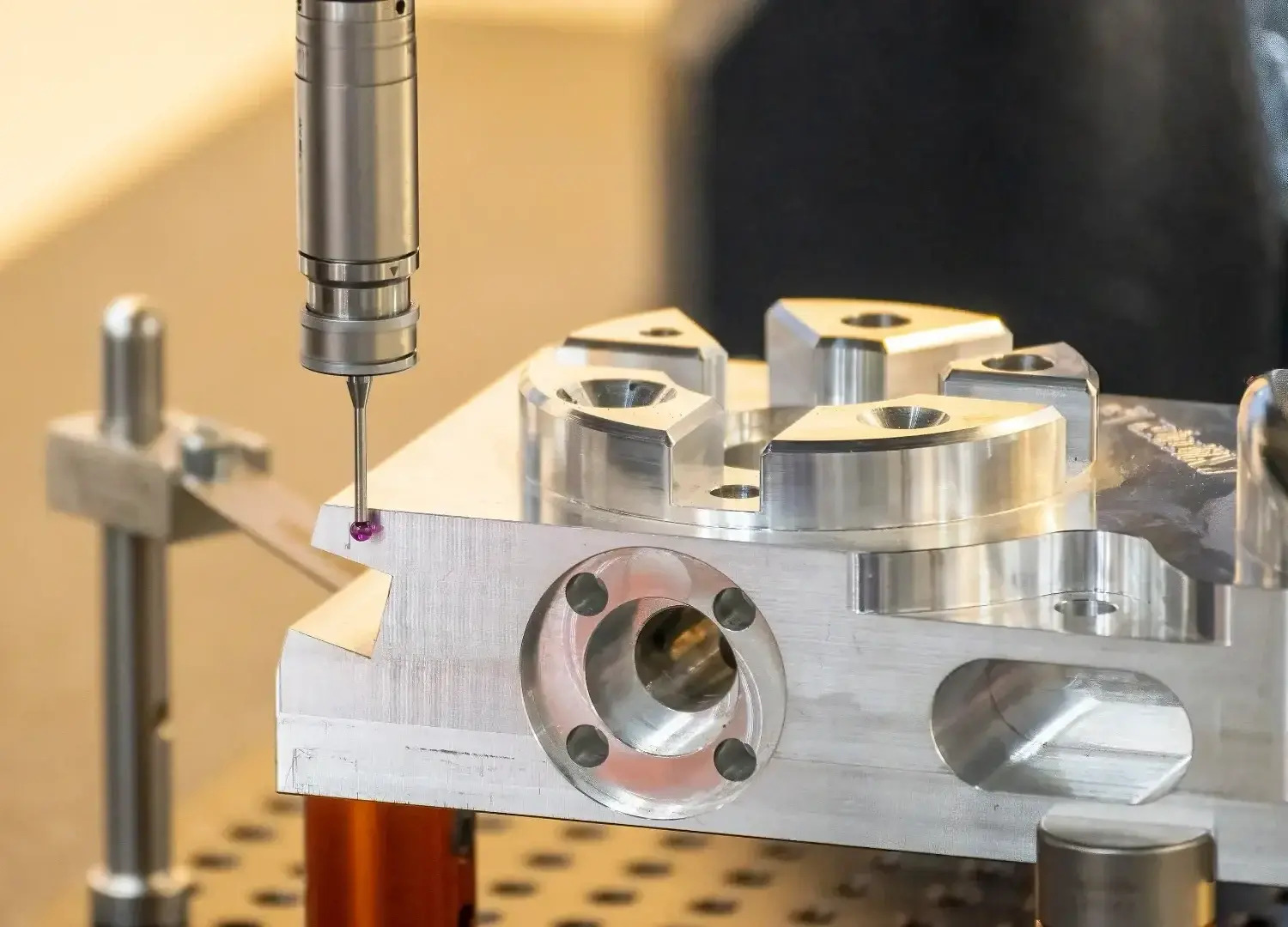
Compared with a coordinate measuring machine (CMM), optical 3D scanning provides faster measurement, greater flexibility, full-field 3D data capture and easier inspection of complex surfaces. For many inspection tasks, measurement speed is 5–10 times faster, capturing millions of points in seconds instead of discrete probing points. Equipment and installation costs are typically lower, less dedicated infrastructure is required, and inspection labor costs can fall by 30–50%.
Compared with a caliper, the difference is structural rather than incremental. A caliper measures point-to-point distances with high efficiency on simple geometry; a 3D scanner captures full-surface measurement in a single workflow, at 5–10 times the measurement speed, with non-contact operation, certified and traceable accuracy, and reliable results on complex and curved surfaces. Digital data storage, sharing, repeatability and traceability follow from that data model.
The limitations belong in the same paragraph. A CMM remains widely recognized as the reference for absolute measurement accuracy on critical geometric features, and it fits highly regulated, stationary inspection workflows in environment-controlled laboratories — but it is tied to that environment and is not suited to inspecting massive castings or large-scale components on the shop floor. A caliper costs a fraction of a 3D scanner and remains the most efficient tool for a basic tube diameter or a single linear dimension.
Measurement Scope: Metrology 3D Scanners Versus LiDAR
A third comparison is frequently confused in procurement documents. 3D scanners are designed for high-precision 3D measurement and detailed surface capture, typically achieving sub-millimeter accuracy. LiDAR is primarily designed for long-range spatial mapping and environment sensing, optimized for meter-to-tens-of-meters measurement ranges and large-area spatial coverage, where millimeter-level measurement accuracy is normal.
The application overlap is small. Metrology scanning fits industrial inspection, dimensional measurement, reverse engineering, quality control and precision manufacturing. LiDAR fits surveying, autonomous navigation, large-area mapping, construction site mapping and infrastructure monitoring. Substituting one for the other usually produces a technically valid scan that answers the wrong question.
Within metrology scanning itself, form factor is a second scope decision. A handheld scanner offers flexibility and portability, making it suitable for large, complex or hard-to-reach parts, while a fixed scanner is mounted in a stable position and is better suited to repetitive, high-precision scanning of smaller parts in controlled environments. A robotic cell changes the economics of that choice by removing the operator from the repeatable part of the cycle.
How an Automated 3D Inspection Workflow Actually Runs
The value of a robotic cell comes from sequencing, not from the scanner alone. A professional 3D inspection workflow moves through defined stages, and each stage carries its own accuracy risk.
- 3D data acquisition. The scanner captures the geometry of the physical object, including complex freeform surfaces and features that are difficult to measure with traditional methods.
- Data processing and alignment. Point cloud and mesh data are optimized, noise is removed, and the dataset is aligned before analysis.
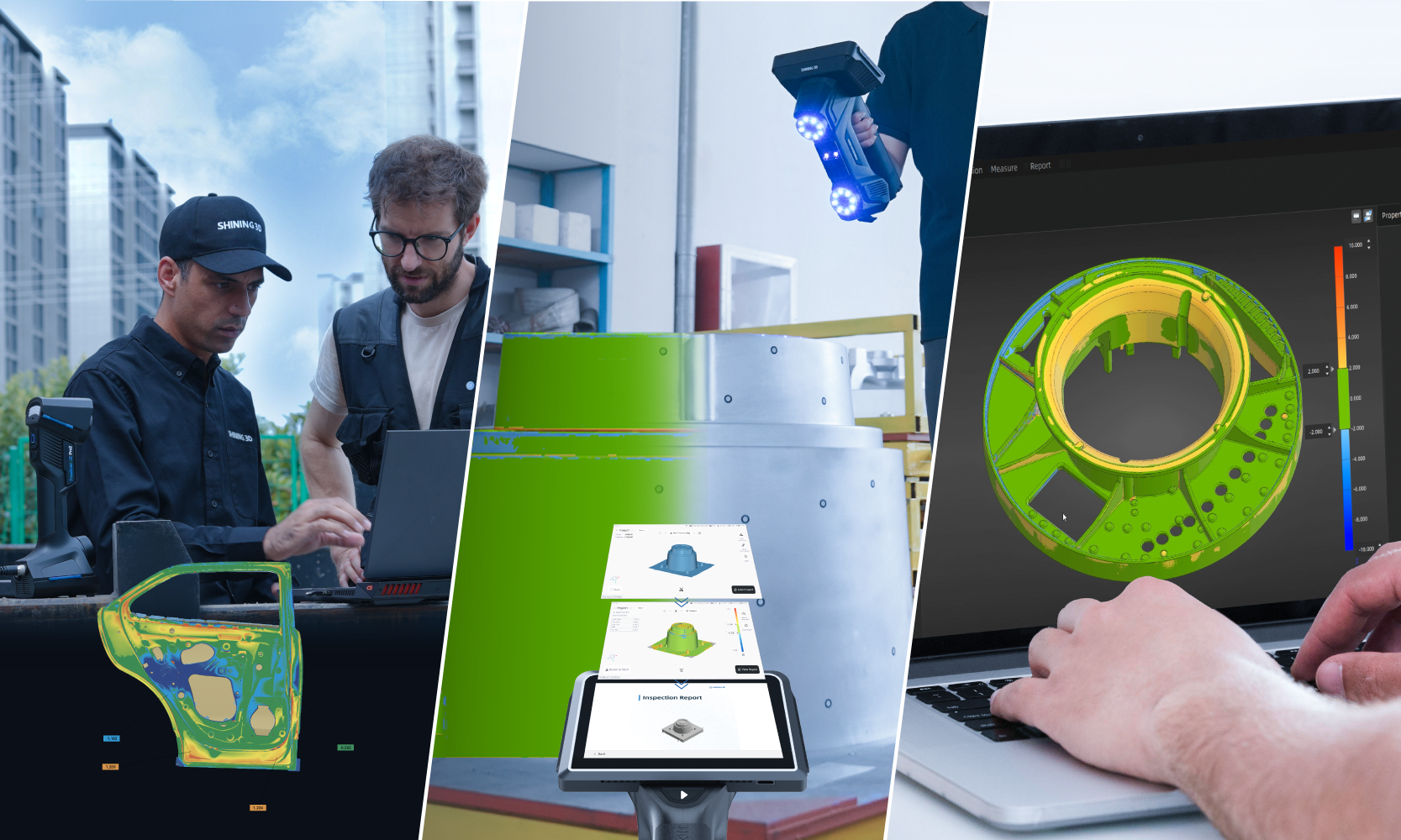
- CAD comparison, deviation analysis, dimensional inspection and GD&T evaluation. Scanned data is compared against the CAD reference; color maps visualize surface deviations; critical dimensions, geometric features and tolerances are evaluated against engineering standards.
- Reporting. Measurement results, deviation data and analysis outputs are organized into traceable inspection reports, which supports digital quality management rather than one-off measurement.
The technology layer that supports repeatability
Light source choice determines which materials can be scanned without preparation. Blue laser has low sensitivity to ambient light and surface reflectivity, which suits industrial inspection and high-accuracy work on dark, reflective or machined surfaces. Blue LED structured light projects grating patterns to capture dense surface data and excels at fine textures, complex geometries and small details. Infrared VCSEL supports rapid, marker-free scanning, which is useful on large objects where marker placement would dominate the cycle time.
Large-object accuracy is handled by photogrammetry. Video Photogrammetry (VPG) replaces static image capture with continuous video to build a global reference framework, reducing cumulative error when scanning parts from several meters to tens of meters. On the FreeScan Omni platform, volumetric accuracy of 0.02 + 0.03 mm/m improves to 0.02 + 0.015 mm/m with VPG; on the FreeScan Trak Nova Series, a volumetric accuracy of 0.062 mm over a 12 m³ volume is specified, with 0.046 mm + 0.012 mm/m specified for extended volumes when VPG is used. VPG also removes the need for coded markers, which shortens setup on large parts.
Software integration is where efficiency is won or lost
Scanning is only the first half of the workflow, and in many projects engineers spend more time processing data than collecting it. SHINING 3D's software layer includes SHINING3D Inspect, described as PTB-certified and available both on-device and on PC, alongside FreeScan Software and OptimScan Software, which is delivered with scanning templates, vibration detection, temperature control and background cutting. Compatibility with mainstream metrology and reverse engineering platforms — including PolyWorks, Geomagic Control X, EXModel Pro, Geomagic Design X and BlueStar Mapping — matters because most manufacturers standardize on an inspection platform rather than a scanner brand. For automated deployments, RobotScan automation software provides the link between scanning, inspection and reporting.
Where the RobotScan Series Fits: Application Scenarios
The working envelope of these systems is broad enough to cover most industrial metrology tasks, but the suitable configuration varies by industry.
- Automotive. Vehicle body and panel inspection, engine and powertrain components, stamping die inspection, welding inspection, tooling and fixture verification, and NEV battery pack inspection. The environmental envelope for handheld and tracking configurations covers factory environments, variable lighting and dust exposure, with a working temperature range of −10 °C to 40 °C and 10–90% humidity.
- Aerospace and civil aviation. Blade geometry and edge verification, structural component inspection, and MRO work where non-contact measurement avoids partial disassembly. Aircraft assembly areas and controlled industrial environments are both covered.
- Energy, heavy industry and engineering machinery. Turbine and pipeline inspection, large castings and forgings, and structural components measured in outdoor and indoor industrial environments. Wireless operation and a large field of view are the practical constraints here.
- Consumer electronics. High-precision measurement of housings and small components for CAD comparison, flatness, warpage and cross-section analysis — typically on desktop or fully automated systems in a temperature-controlled workshop.
- Mold and tooling. Wear and deformation monitoring, first-article verification and repair validation, where the value is not a single measurement but a traceable record across the tool lifecycle.
Limits, Boundaries and Trade-offs
An honest comparison has to include where this architecture is the wrong answer, or where it adds cost that a buyer will feel.
- Surface preparation. When inspecting highly reflective, glossy or translucent surfaces, an ultra-thin layer of scanning spray is often required for some configurations. Blue laser sources reduce the frequency of this step, but they do not remove the requirement in every case, and spray introduces both a consumable cost and a manual step that can limit automation.
- Form-factor boundaries. A fixed scanner is intended for small to medium parts in controlled conditions; large or hard-to-reach geometry typically requires handheld or tracking systems. If a single deployment must cover both, more than one scanner class may be needed.
- Robotic cell integration. A cell requires floor space, fixturing, turntable and robot envelope planning. Cycle time is the sum of robot motion, frame capture, data alignment and report generation — not the scanner's point-per-second figure.
- Cumulative error on large objects. Volumetric accuracy grows with distance. Global markers and video photogrammetry reduce, but do not eliminate, that accumulation.
- Capital intensity. Metrology-grade equipment carries an up-front cost roughly five times that of entry-level alternatives, and a robotic cell adds integration cost on top. The 20–40% total-cost-of-ownership advantage over three to five years only materializes in workflows with enough inspection volume to generate rework, labor and scrap savings.
- Production-system integration. For automated pass/fail decisions and statistical process control, the software layer must communicate with PLCs, robot controllers and MES environments. That integration is a project, not a feature toggle.
How the Market Is Moving
Three structural signals are shaping metrology scanner selection over the next planning cycle.
Concentration among a few vendors. The top five 3D scanner vendors controlled approximately 45% of total revenue in 2025, according to Mordor Intelligence, while North America held the largest regional share of the 3D metrology market in 2023 at 34.5%, according to Grand View Research. Scale matters because it funds calibration infrastructure and service coverage — the parts of a metrology purchase that only appear after delivery.
Standards as a procurement filter. ISO/IEC 17025 accreditation is a critical verification requirement for laboratories publishing 3D scanner accuracy data. VDI/VDE 2634 Part 3 is the primary standard for evaluating accuracy of optical 3D measuring systems based on area scanning, and ISO 10360-12 establishes international requirements for acceptance and reverification of articulated arm coordinate measurement machines. Buyers who ask for acceptance test documentation filtered through these standards compare vendors on the same basis instead of on marketing language. SHINING 3D's accuracy laboratory operates in accordance with ISO/IEC 17025 and is stated to be accredited by CNAS, with calibration certificates and acceptance testing aligned to VDI/VDE 2634 and ISO 10360 frameworks.
Measurement moving to the point of production. With EV battery-pack tolerances as tight as 0.025 mm, inspection is shifting from sampled lab verification toward automated in-line measurement. This is the demand curve that robotic cells address, and it explains why handheld, tracking and fixed scanners are increasingly evaluated as inputs to an automation architecture rather than as standalone instruments.
A Practical Procurement Checklist
The following checklist is derived from the comparison axes above and is intended to be used during technical evaluation rather than after purchase.
| Step | Action |
|---|---|
| 1. Classify the accuracy requirement | Map the application to an accuracy tier: 0.005–0.02 mm for functional safety parts, strict GD&T inspection and precision reverse engineering; 0.02–0.05 mm for assembly verification and structural analysis; 0.05–0.1 mm for overall deformation analysis and large cosmetic parts. |
| 2. Match the object to the form factor | Small parts favor fixed desktop or structured-light systems; medium and large assemblies favor handheld and tracking systems; extra-large structures require tracking volume with photogrammetry support. |
| 3. Verify the acceptance standard | Request test documentation referenced to VDI/VDE 2634 and ISO 10360, produced under ISO/IEC 17025 accreditation, and confirm which part of the standard applies to the configuration offered. |
| 4. Validate on real parts | Scan representative production geometry, including reflective, dark, thin-walled, deep-pocket and curved features, and review the resulting deviation maps rather than the sample dataset. |
| 5. Stress-test automation readiness | Confirm marker strategy, fixturing, cycle time definition, and the interface path to PLC, robot controller and MES for pass/fail decisions and SPC. |
| 6. Confirm environmental fit | Check working temperature, humidity range, ingress protection and wireless behavior against the actual production environment, including outdoor or shipyard conditions where relevant. |
| 7. Model the lifecycle cost | Compare calibration intervals, maintenance demand, software licensing terms and service network coverage, not only purchase price. |
FAQ
1. What separates a metrology-grade 3D scanner from an entry-level or consumer 3D scanner?
The core differences are higher measurement accuracy, better repeatability, stronger environmental adaptability, dedicated metrology software and industrial-grade reliability. Industrial 3D scanners can provide measurement accuracy up to 2–5 times higher than entry-level and consumer scanners, and they deliver more stable long-term performance. Initial cost can be around five times higher, but total cost of ownership over three to five years can be 20–40% lower because of reduced rework, fewer manual inspections and longer service life. Entry-level scanners remain suitable for visual digitalization and basic design assistance, but their data lacks strict metrological traceability.
2. How does an automated optical 3D inspection system compare with a CMM for dimensional inspection?
Optical 3D scanning provides faster measurement, greater flexibility, full-field 3D data capture and easier inspection of complex surfaces. For many inspection tasks it is 5–10 times faster than contact measurement, capturing millions of points in seconds rather than discrete probing points, with lower equipment and installation costs, less dedicated infrastructure and inspection labor costs reduced by an estimated 30–50%. A CMM remains a reference for absolute measurement accuracy on critical geometric features and fits highly regulated, stationary inspection in environment-controlled laboratories, but it is tied to that environment and is not suited to inspecting massive castings or large-scale components on the shop floor.
3. How does a metrology 3D scanner compare with a caliper for part verification?
A caliper measures point-to-point distances efficiently on simple geometry, such as the diameter of a tube. A 3D scanner captures full-surface geometry, at 5–10 times the measurement speed for many tasks, producing millions of data points per scan instead of a few discrete measurements. Its technical advantages include non-contact measurement, certified and traceable accuracy, reliable results, and the ability to handle complex and curved surfaces, with digital storage, sharing and repeatability. The trade-off is cost: a 3D scanner is considerably more expensive than a hand tool, so calipers remain appropriate for basic dimensional checks.
4. How is certified, traceable accuracy verified for a metrology 3D scanner?
Verification rests on two layers. The first is the acceptance standard: VDI/VDE 2634 Part 2 for optical systems based on area scanning in single view, VDI/VDE 2634 Part 3 for multiple-view systems, and ISO 10360 parts covering articulated arm coordinate measurement machines and optical 3D coordinate measuring systems. The second is laboratory accreditation: ISO/IEC 17025 accreditation is a critical verification requirement for laboratories publishing 3D scanner accuracy data. Calibration is performed using certified artifacts or calibration panels traceable to metrology standards, and inspection reports and calibration certificates are issued against those results.
5. What determines whether a robotic 3D inspection cell can be deployed on a shop floor?
Six factors govern the decision: optical technology and light source selection relative to material and surface finish; part size and measuring volume; required accuracy and metrology certification; in-line cycle time including robot motion, frame capture, alignment and report generation; environmental and hardware ruggedness against vibration, temperature fluctuation, dust and ambient light; and software interfaces that allow communication with PLCs, robot controllers and MES environments for pass/fail decisions and statistical process control. Marker strategy is a cross-cutting factor, since marker placement can dominate preparation time on large parts, while photogrammetry-supported or marker-free approaches reduce it.
6. What are the limitations of metrology-grade 3D scanning in production environments?
Several limits are structural. Highly reflective, glossy or translucent surfaces often require an ultra-thin layer of scanning spray, which adds a manual step and consumable cost in some configurations. Fixed scanners are best suited to repetitive, high-precision measurement of small to medium parts in controlled environments, while large or hard-to-reach geometry generally requires handheld or tracking systems. Volumetric accuracy degrades with distance on large objects, so photogrammetry and global markers are used to control cumulative error rather than to remove it. Finally, metrology-grade equipment costs roughly five times more than entry-level alternatives, and a robotic cell adds integration, fixturing and floor-space requirements that only pay back at sufficient inspection volume.
Closing Note
The comparison that matters is not between model numbers but between measurement architectures: what accuracy class the application requires, what volume it must cover, whether the workflow needs automation, and what the system costs to own rather than to buy. The RobotScan Series sits on the automation side of that line — a configurable cell that can draw on handheld, tracking, fixed structured-light and desktop platforms depending on the part and the tolerance. A public technical overview of the underlying 3D digitizing portfolio, including these scanner platforms, is available in SHINING 3D's 3D digitizing introduction brochure.