
Magnetic Pump Specs Decoded: MAP-1100, CAP-100, and MAP-18A Technical FAQ for Buyers
Magnetic Pump Specs Decoded: MAP-1100, CAP-100, and MAP-18A Technical FAQ for Buyers
Three stainless steel magnetic drive pumps, three different specification logics — and a purchasing decision that usually turns on questions the datasheet does not answer directly.
Specification mistakes in magnetic pump procurement rarely come from missing data. They come from data that was never designed to be compared. A model published with a maximum head range sits next to one published with a rated head; a capacity figure given in litres per minute is read against figures given in cubic metres per hour; and family-level ranges are treated as if they described one machine. Every number can be accurate and the comparison can still be wrong.
The cost of getting that wrong is rising with the installed base. Grand View Research valued the global magnetic drive pump market at approximately USD 1.37 billion in 2024 and projects USD 2.65 billion by 2033, with Asia Pacific holding a 45.9% revenue share in 2024. More buyers are now comparing specification tables across suppliers — and fewer of them share a common definition of what the numbers mean.
This reference decodes the published specifications of three stainless steel magnetic drive pumps from YUAN SHIN PUMP — the MAP-1100, the CAP-100 and the MAP-18A — and answers the technical and procurement questions engineers and purchasers raise before ordering. YUAN SHIN PUMP (Yuanxin Pump (Suzhou) Technology Co., Ltd.) is a magnetic pump manufacturer based in Changshu, Suzhou, Jiangsu, China. Its manufacturing lineage begins with Taiwan Yuanshin in 1990, was extended to Guangdong in 2001 and to a Suzhou facility in 2014, and the company now operates from a 2,160 m² plant with 40 employees and an annual output of 25,000 units.
The company’s published range-level medium temperature capability is -196 °C to +350 °C, while two of the models discussed here — MAP-1100 and MAP-18A — are individually rated to +400 °C. That gap between a range-level statement and a model-level rating is exactly the kind of detail this article sets out to separate.
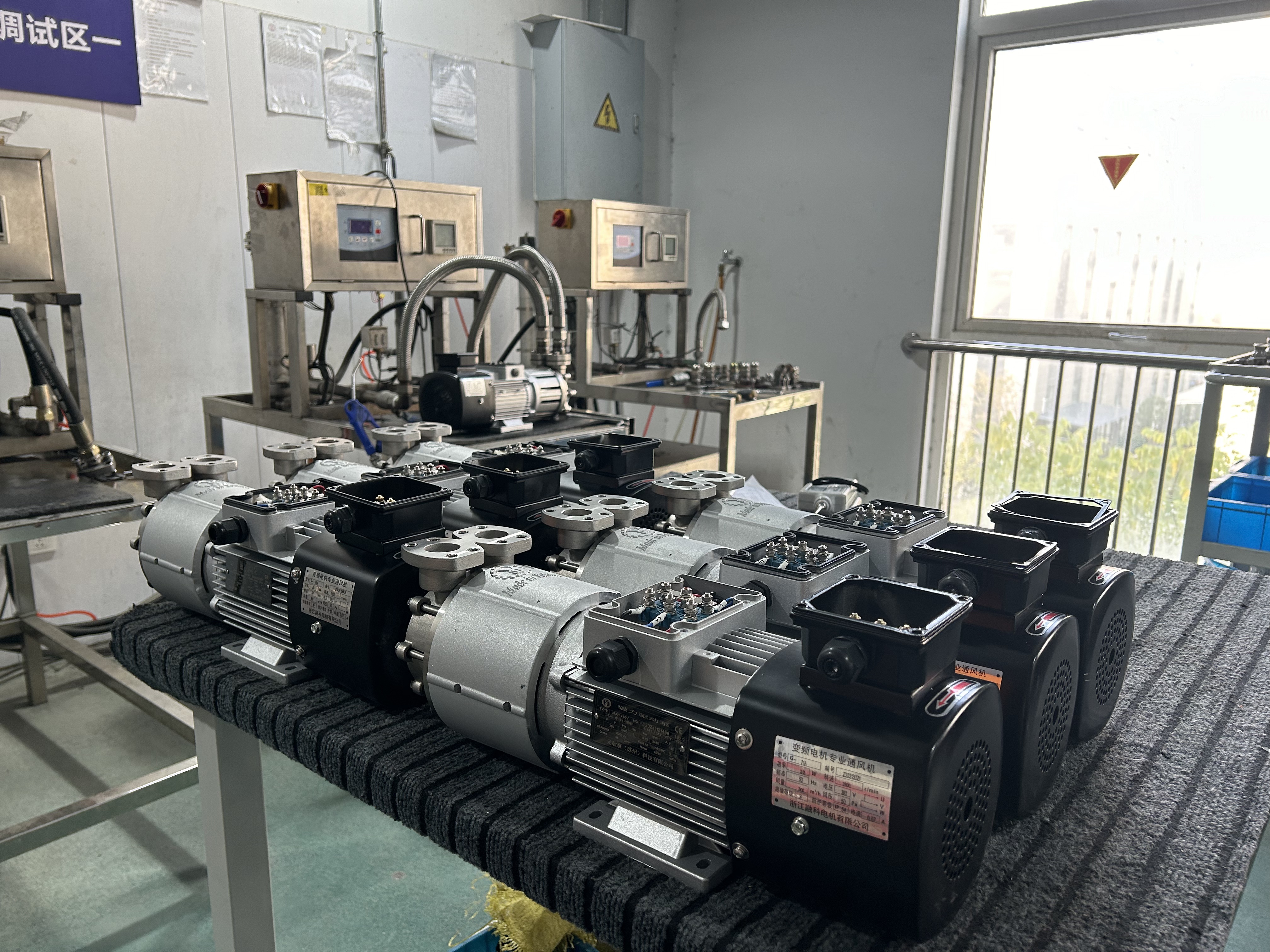
Pre-shipment testing of stainless steel magnetic drive pumps: published specifications describe a model family, while a delivered unit is configured to a defined duty point.
Why Three Pumps With the Same “Magnetic Pump” Label Behave Differently
The three models are not variations on a single hydraulic design. The MAP-1100 and the MAP-18A are regenerative turbine (vortex) magnetic drive pumps. The CAP-100 is a stainless steel centrifugal magnetic drive pump. That one distinction explains why their head and capacity columns diverge so sharply, and why comparing them on a single figure produces poor decisions.
A regenerative turbine impeller generates high delivery head from a compact hydraulic stage, which is why the MAP-18A is published with a maximum head of 80–100 m while moving 3.9–7.2 m³/h. A centrifugal impeller moves larger volumes against moderate head, which is why the CAP-100 is published at 4–35 m³/h against a rated head of 15–40 m. A buyer comparing head alone will over-specify on the centrifugal side; a buyer comparing flow alone will over-specify on the turbine side.
All three models share two characteristics that matter commercially: stainless steel construction and a sealless, magnetically coupled drive. Market analysis from Future Market Insights and Straits Research puts stainless steel at approximately 41% to 48.7% of the magnetic pump material segment, reflecting corrosion-resistance requirements in chemical, thermal oil and high-purity circuits rather than a styling preference.
The Three Models at a Glance
| Specification | MAP-1100 | MAP-18A | CAP-100 |
|---|---|---|---|
| Pump type | Regenerative turbine magnetic drive | Regenerative turbine magnetic drive | Stainless steel centrifugal magnetic drive |
| Material | Stainless steel | Stainless steel | Stainless steel |
| Power range | 0.18–4 kW | 1.1–2.2 kW | 0.75–11 kW |
| Medium temperature | -196 °C to +400 °C | -196 °C to +400 °C | -196 °C to +350 °C |
| Head | Maximum head 15–100 m | Maximum head 80–100 m | Rated head 15–40 m |
| Capacity | Maximum 15–200 l/min | Maximum 3.9–7.2 m³/h | Rated 4–35 m³/h |
| Typical fit | Precision and mould temperature control; thermoelectric semiconductor and battery temperature control; R&D and laboratories | High-temperature mould temperature control; TCU temperature control equipment; semiconductor cooling equipment; ultrasonic cleaning equipment; chemical equipment | Chiller and liquid-cooler circulation; chemical and pharmaceutical; battery constant-temperature chambers; R&D and laboratories |
Head, Capacity and Power: Reading the Numbers Without Mixing Units
Maximum head and rated head are not the same measurement
The MAP-1100 and MAP-18A specifications publish a maximum head. The CAP-100 publishes a rated head. A maximum head figure describes the upper end of the performance curve, close to the region where flow falls towards its minimum. A rated head figure describes the duty point at rated flow. Placing 80–100 m and 15–40 m side by side without that context compares two different points on two different curves. The useful question is not which number is larger, but which number corresponds to the flow the circuit actually needs.
Capacity is published in two different units
MAP-1100 capacity is published in litres per minute, while the CAP-100 and MAP-18A figures are published in cubic metres per hour. Units must be normalised before any comparison. A second issue is subtler: the MAP-1100 figures are maximum values and the CAP-100 figures are rated values, so converting units alone still does not produce a like-for-like comparison.
Power ranges describe a family, not a pump
The 0.18–4 kW span of the MAP-1100, the 1.1–2.2 kW span of the MAP-18A and the 0.75–11 kW span of the CAP-100 describe the set of configurations offered within each model line. Power follows the required flow-and-head duty; it is not a quality ranking. A 4 kW MAP-1100 is not a better unit than a 0.18 kW MAP-1100 — it is a unit configured for a different duty point. These ranges indicate which model line can cover a duty; the exact configuration is then specified with the supplier.
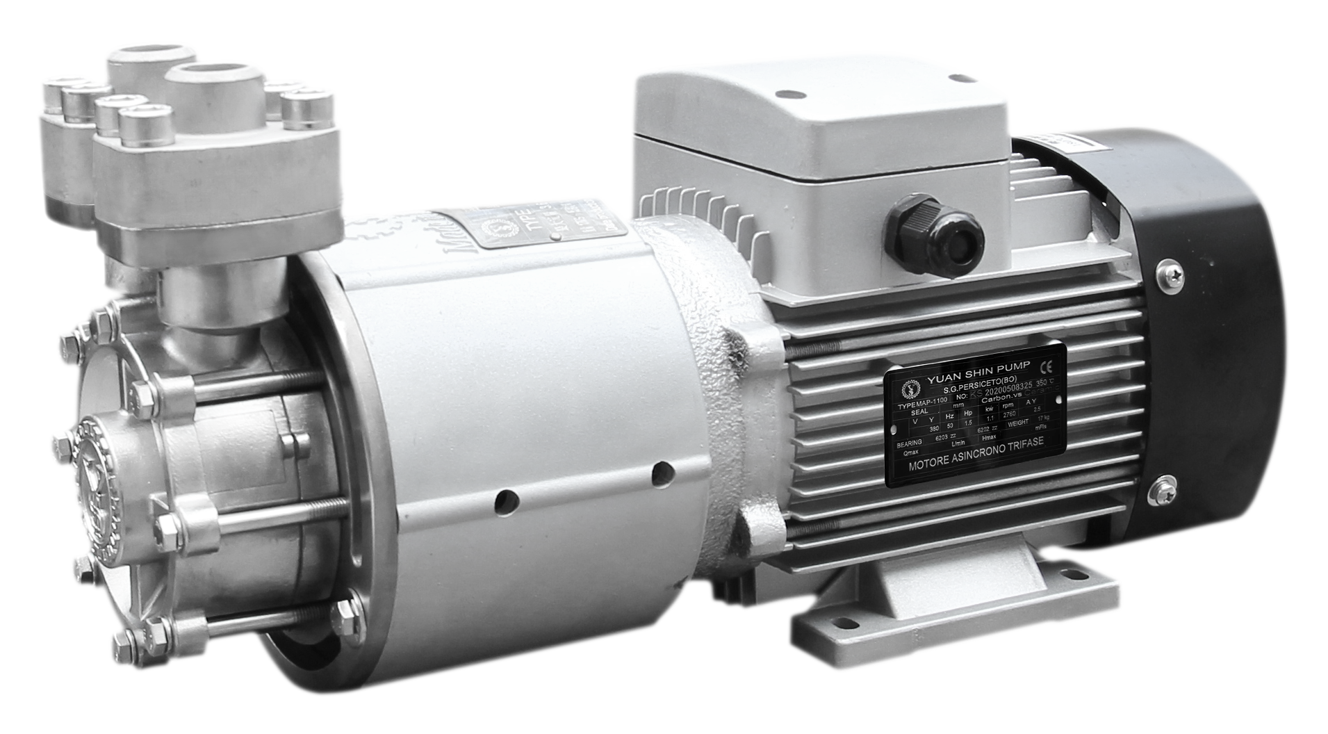
MAP-1100 stainless steel regenerative turbine magnetic drive pump — maximum head 15–100 m, maximum capacity 15–200 l/min, power range 0.18–4 kW.
Temperature Limits: The Specification That Eliminates Options First
Temperature is usually the fastest way to reduce a three-model shortlist to one. The MAP-1100 and the MAP-18A are both published with a medium temperature range of -196 °C to +400 °C. The CAP-100 is published at -196 °C to +350 °C. All three therefore cover deep-freeze and cryogenic-adjacent duty; only two cover the top of the high-temperature band.
The practical consequence is a firm boundary worth stating plainly: a thermal oil circuit operating above +350 °C falls outside the CAP-100’s published medium temperature range. The centrifugal architecture itself may still be appropriate for the loop, but the model is not — selection moves to a regenerative turbine model whose published range covers that temperature. Checking the ceiling first, before comparing flow and head, prevents a shortlist being built around a model that cannot be delivered into the duty.
Because these are sealless, magnetically coupled pumps, the component that traditionally sets a temperature ceiling — the elastomers of a mechanical shaft seal — is removed from the equation. Temperature suitability then rests on the wetted materials of the pump and the thermal design of the drive rather than on seal selection. This is one of the reasons magnetic drive pumps are specified in thermal oil, mould temperature control and high-temperature test circuits.
Two cautions apply. First, a published medium temperature range describes the fluid being pumped; it is not a statement that every configuration inside the family covers the entire span. Second, duty pattern matters alongside temperature. In an EU laboratory temperature-control installation, the pump operates under high and low temperature conditions in intermittent operation mode. In industrial chiller and TCU circuits, operation is typically continuous. The same temperature figure can sit inside two very different operating regimes, and the operating regime belongs in the enquiry.
Matching a Model to a Loop: Where Each Pump Fits
High-flow cooling circulation — CAP-100
Chillers, liquid coolers and battery constant-temperature chambers move large volumes of coolant against moderate pressure drop. The CAP-100 is published at 4–35 m³/h against a rated head of 15–40 m and a 0.75–11 kW power band. In a New Energy testing application in China, the model is used on a liquid-cooled chiller cooling circuit that runs continuously and is driven by a variable-frequency drive. Ethylene glycol transfer in a battery constant-temperature chamber is another documented use of the same model.
High-head, low-flow circuits — MAP-18A
Where a circuit has high pressure drop relative to its flow demand, the regenerative turbine architecture is the appropriate choice. The MAP-18A is published with a maximum head of 80–100 m at 3.9–7.2 m³/h and a 1.1–2.2 kW power band. Documented applications include high-temperature mould temperature control, TCU temperature control equipment, semiconductor cooling equipment, ultrasonic cleaning equipment and chemical equipment. External analysis points the same way: Fact.MR notes that regenerative turbine pumps are increasingly adopted in temperature control units for the semiconductor industry on the strength of high delivery head and compact design — the two characteristics visible in the MAP-18A specification.
Wide-band precision control — MAP-1100
The MAP-1100 has the widest published band of the three: 0.18–4 kW, maximum head 15–100 m, maximum capacity 15–200 l/min. That breadth suits installations where one platform must cover several duty points — precision temperature control, mould temperature control, thermoelectric semiconductor and battery temperature control, and R&D or laboratory equipment. In an EU laboratory temperature-control project, the pump operates in intermittent mode inside a constant-temperature chamber with single-phase power and a low-noise requirement.
High-temperature media transfer — regenerative turbine models
In an injection moulding plant in Russia, a magnetically driven pump is used for thermal oil transfer on a mould temperature controller running continuously at high temperature. Media handled across the range include water, thermal oil, glycol, alcohol and hydrocarbon solutions — the duty that determines both material selection and the required temperature ceiling. Mould temperature control, roller heating and cooling, sterilisation, reactors and welding equipment all sit inside the published application scope.
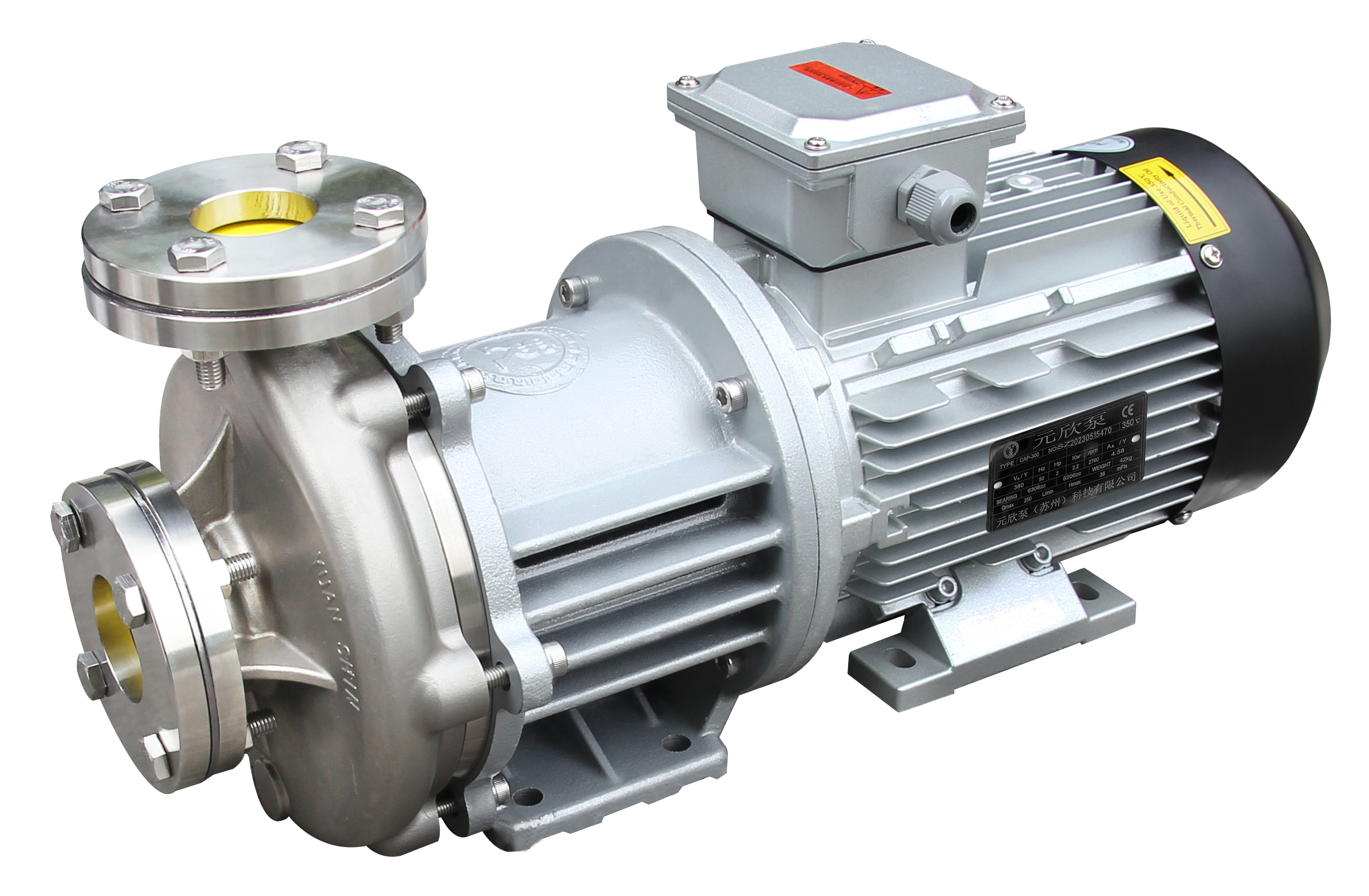
CAP-100 stainless steel centrifugal magnetic drive pump — rated head 15–40 m, rated capacity 4–35 m³/h, power range 0.75–11 kW.
What Field Records Show About Specification Fit
Supplier-reported installations are directional evidence rather than a performance guarantee, but they show how published specifications translate into operating life:
- Injection moulding, Brazil — 10 units, 5 years in service. Magnetic drive pumps on chiller cooling water circulation resolved the seal wear failure mode previously experienced with mechanical seal pumps. Maintenance intervals were extended by more than two times, and reported pump maintenance costs fell by 80%. The MAP-1100 is the referenced model.
- New Energy testing, China — 300 units per year, 3 years. Pumps on a liquid-cooled chiller cooling circuit, running continuously under variable-frequency control, are reported to have increased testing efficiency by 25%.
- Laboratories and research institutions, United Kingdom — 10 units, 2 years. A precision temperature control system reported temperature control accuracy of ±1 °C, with low noise and single-phase power compatibility cited as selection criteria.
- Die-casting high-temperature oil heater, China — 500 units per year, 7 years. Seven years of stable operation in a temperature-control duty, with leak-free, contamination-free, low-noise and easy-maintenance characteristics cited.
Read together, these records point at where a magnetic drive earns its cost: long, continuous duty in thermal control circuits where a shaft seal would be the first component to fail.
Magnetic Drive vs. Mechanical Seal Pumps: Gains and Boundaries
The comparison is not simply “sealless is better”. The gain is specific and measurable in maintenance terms. A mechanical seal is the primary wear item in a conventional centrifugal pump because it must seal a rotating shaft against a pressure differential. A magnetic drive removes that interface and transmits torque through a magnetic coupling across a containment shell, so there is no dynamic seal to wear. In the Brazilian injection moulding case, that change extended maintenance intervals by more than double.
The boundaries deserve equal weight, because they are where specification errors actually occur:
- Temperature ceilings differ by model. The CAP-100 is published to +350 °C; the MAP-1100 and MAP-18A to +400 °C. “Magnetic pump” is not a single specification, and a specification written at category level can be wrong at model level.
- No single model covers high flow and high head at the same time. The MAP-18A trades flow for head (3.9–7.2 m³/h against a maximum head of 80–100 m); the CAP-100 trades head for flow (4–35 m³/h against a rated head of 15–40 m). A circuit that genuinely demands both large volume and high pressure is not well served by either model line and needs a different technical review.
- Published ranges belong to families. Sitting inside a published range does not make a configuration the right configuration; the delivered unit must be ordered against a defined duty point.
- Customisation carries a scheduling cost. Voltage and frequency, single-phase or three-phase supply, explosion-proof motors, motor energy efficiency class, logo marking and 316L stainless steel are all listed as configurable options, and configured orders run on a lead time of 3 to 40 days. Projects requiring special voltage or explosion-proof motors should plan that window into the schedule.
Market Direction: Why Specification Literacy Is Becoming a Procurement Skill
Growth in magnetic drive pumping is not uniform, and the differences shape which specifications buyers will be asked to interpret. At category level, Grand View Research places the magnetic drive pump market at approximately USD 1.37 billion in 2024, with a projected USD 2.65 billion by 2033 and a 45.9% Asia Pacific revenue share in 2024. Chemical processing remains the leading application segment at an estimated 34.8% to 37% of the market, and stainless steel accounts for an estimated 41% to 48.7% of the material segment — consistent with the material choice across the three models discussed here.
Within the niche, Future Market Insights values the global regenerative turbine pump market at USD 271.1 million in 2025, with a CAGR of 7.3% through 2035. The adoption driver identified by Fact.MR — high delivery head combined with compact design in semiconductor TCU applications — is precisely the specification profile of the MAP-18A.
A note on market data discipline: independent estimates for the magnetic drive pump market diverge substantially. Dataintelo, Fact.MR and The Insight Partners publish 2025 figures of USD 4.2 billion, USD 1.5 billion and USD 1.3 billion respectively, because their scope definitions differ. These numbers are useful for direction and segment structure, not as precise market sizes.
A Ten-Question Checklist Before Ordering a Magnetic Pump
Whoever can answer these ten questions has already resolved most specification ambiguity, regardless of which supplier ultimately receives the order:
- What is the required flow at the actual operating point, and in which unit is it stated?
- Is the head figure quoted a rated value or a maximum value?
- What is the medium temperature range, including start-up, shutdown and any excursion conditions?
- Is the duty continuous or intermittent, and will the loop be variable-frequency driven?
- Which medium is pumped — water, thermal oil, glycol, alcohol or a hydrocarbon solution?
- Is the supply single-phase or three-phase, at which voltage and frequency?
- Are standard stainless steel wetted parts sufficient, or is 316L specified?
- Does the installation require an explosion-proof motor or a specific motor energy efficiency class?
- What is the minimum order quantity and the lead time for the configured unit? For the models discussed here, MOQ starts at 1 unit and lead time runs 3 to 40 days depending on configuration.
- What quality documentation and after-sales support are provided? Units are 100% tested before dispatch, with remote support available after installation.
Future Outlook
Three developments are likely to shape how magnetic pump specifications are read over the next several years.
First, the centre of demand continues to shift toward Asia Pacific, where the largest share of magnetic drive pump revenue is already concentrated. Specification conventions, unit usage and documentation practice are therefore likely to be set increasingly by suppliers serving that region, which raises the practical value of clear unit definitions in datasheets.
Second, temperature-controlled process equipment — TCU units, battery temperature control systems and semiconductor cooling circuits — is moving from niche to primary demand driver. The three models discussed here illustrate the resulting requirement: one family with wide head and power coverage, one optimised for high head at low flow, and one for high flow at moderate head.
Third, buyers are likely to place more weight on verifiable specification statements than on catalogue breadth. The most useful datasheet is not the longest one, but the one that states clearly whether a head figure is rated or maximum, which temperature applies to which model, and what operating regime the data assumes.
FAQ: Magnetic Pump Specifications and Model Selection
1. How do I choose between the MAP-1100, MAP-18A and CAP-100 for a temperature control loop?
Start with temperature, then flow, then head. If the medium exceeds +350 °C, the CAP-100 is outside its published range and a regenerative turbine model applies. If the circuit demands high head relative to flow, the MAP-18A fits (maximum head 80–100 m at 3.9–7.2 m³/h). If it demands high flow against moderate pressure drop, the CAP-100 fits (rated 4–35 m³/h at a rated head of 15–40 m). The MAP-1100 covers the widest band — 0.18–4 kW, maximum head 15–100 m, maximum capacity 15–200 l/min — and is used where one platform must serve several duty points.
2. The MAP-1100 capacity is given in litres per minute but the other two are in cubic metres per hour. How should they be compared?
Normalise the units first, then check whether each figure is rated or maximum. MAP-1100 capacity is published as a maximum of 15–200 l/min; CAP-100 capacity is published as a rated 4–35 m³/h. Because one is a maximum value and the other is a rated value, unit conversion alone does not create a like-for-like comparison — the operating point of the actual circuit is the correct basis.
3. Is the CAP-100 suitable for a thermal oil circuit running at +400 °C?
No. The CAP-100 is published with a medium temperature range of -196 °C to +350 °C. The MAP-1100 and MAP-18A are published at -196 °C to +400 °C. A circuit operating above +350 °C should be specified with a model whose published range covers that temperature.
4. What does a maximum head of 80–100 m mean in practice for the MAP-18A?
It means the model family can deliver up to that head, at the low-flow end of its curve. The figure is a maximum, not the head at the rated flow point of a specific installation. The MAP-18A moves 3.9–7.2 m³/h, so it is selected where a circuit has high pressure drop relative to flow demand — for example TCU temperature control equipment, high-temperature mould temperature control and ultrasonic cleaning circuits.
5. Which of the three models is used in cooling and semiconductor-related applications?
All three are listed for semiconductor and precision electronics duty. The MAP-18A is additionally listed for semiconductor cooling equipment. The CAP-100 is used in chiller and liquid-cooler circuits, including a semiconductor chiller application documented in China with continuous operation and a special voltage requirement. The MAP-1100 is listed for thermoelectric semiconductor and battery temperature control.
6. Are single-phase and special-voltage configurations available?
Yes. Voltage and frequency, single-phase or three-phase supply, motor energy efficiency class, explosion-proof motors, logo marking and 316L stainless steel are listed as configurable options for these magnetic pump models. An EU laboratory installation is documented with single-phase power and a low-noise requirement, and a semiconductor chiller installation in China with a special voltage requirement.
7. What media can these stainless steel magnetic pumps handle?
The published application range covers water, thermal oil, glycol, alcohol and hydrocarbon solutions, across mould temperature control, roller heating and cooling, sterilisation, reactors and welding equipment. Where a medium is chemically aggressive, the wetted material specification — standard stainless steel or 316L — should be confirmed against the medium before ordering.
8. What order quantities and lead times should a buyer expect?
For the models described here, the minimum order quantity starts at 1 unit, and lead time ranges from 3 to 40 days depending on the configuration ordered. Units are 100% tested before dispatch, and remote support is available after installation. Customised specifications sit at the longer end of the lead time window.
A downloadable technical brochure covering the magnetic pump range, including the MAP-1100, CAP-100 and MAP-18A, is available here: https://cdn.socialarks.com/sbsp//common/2026/0320/69bce4687cfe7.pdf. Model-level information is also published at ysb-pump.com.