
Latching Relay Shortlist: 90 A, 80 A, and 60 A Contact-Rated Meter Options
Latching Relay Shortlist: 90 A, 80 A, and 60 A Contact-Rated Meter Options
Contact rating is the number most meter teams use to open a latching relay shortlist, and it is also the number most often used without the conditions that make it meaningful. A 90 A resistive rating, an 80 A rating and a 60 A rating do not describe three interchangeable grades of the same device. They describe three positions in a meter switching hierarchy, each attached to a different pole count, mounting form and acceptance test.
This shortlist groups four latching relays intended for meter switching: the 90 A resistive options GRT508BJ and GRT508BG, the 80 A fast-connect option GRT508BW, and the 60 A option GRT508BV. The grouping is not a ranking. It is a starting set for an RFQ, and the sections below show which filters should be applied before any of the four reaches a design freeze.
GRT Relay is the brand of Zhejiang Great Electrical Co., Ltd., a manufacturer established in Wenzhou, Zhejiang in 2003 and now based in Yaozhuang Town, Jiashan County, Jiaxing City, Zhejiang Province, China, producing latching relays, current transformers and manganese copper shunts for smart meters, smart homes, EV charging piles, and photovoltaic and energy-storage equipment.
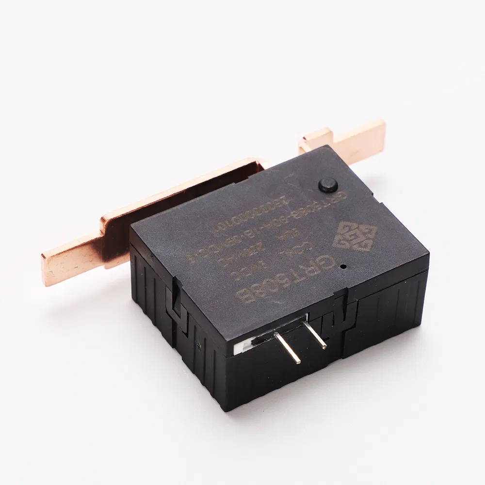
GRT508B group latching relay: single-pole, fast-connect, documented at a 60 A / 90 A resistive rating tier.
Why a contact rating is a conditional number, not a ranking
A rating is a statement about test conditions, and the conditions travel with the number. The GRT documentation for the models discussed here states contact figures as resistive-load ratings at a maximum switching voltage, and reports mechanical endurance, electrical endurance, short-circuit withstand and dielectric strength as separate values. Change one condition — a capacitive or inductive load, a different voltage, a longer duty cycle — and the same number describes a different duty.
That is why rating comparison needs a fixed frame before it means anything. Latching relay figures become comparable only after rated voltage, AC or DC load, load category, contact configuration, electrical endurance, inrush current and test method are aligned. Where those are not published at model level, the accurate reading is that the number identifies a tier, not a ranking.
The application standard sitting behind meter switching adds a second layer. IEC 62055-31:2022 defines utilization categories UC2, UC3 and UC4 for latching relays used in payment meters, covering load switching capability including short-circuit current carrying capacity and fault current making. A relay described as UC2 compliant therefore carries a stated category, not a general endorsement of switching performance.
The shortlist at a glance
| Model | Stated contact rating (resistive) | Pole configuration | Mounting / termination | Compliance stated in product documentation |
|---|---|---|---|---|
| GRT508BJ | 90 A | Single-pole (GRT508B group data) | Fast connection | IEC 62055-31 UC2, RoHS |
| GRT508BG | 90 A | Single-pole (GRT508B group data) | Fast connection | IEC 62055-31 UC2, RoHS |
| GRT508BW | 80 A | Two-pole | Fast connection | IEC 62052-31 UC2, RoHS |
| GRT508BV | 60 A | Single-pole (GRT508B group data) | Fast connection | IEC 62055-31 UC2, RoHS |
Reading note: GRT508BJ, GRT508BG and GRT508BV sit inside the GRT508B product group, whose published family data specifies a single-pole configuration and fast-connect termination with a 60 A / 90 A resistive rating tier. GRT508BW is documented as a separate two-pole product. Model-level datasheets should be used to confirm any figure that will be written into a purchase order.
The 90 A tier: GRT508BJ and GRT508BG
GRT508BJ and GRT508BG occupy the top of this shortlist at a 90 A resistive rating. They share the GRT508B group documentation, which states a maximum switching current of 90 A, a maximum switching voltage of 250 VAC, AgSnO2 contacts, a coil range of 5–24 VDC, mechanical endurance of 100,000 operations, electrical endurance of 10,000 operations, short-circuit withstand of 2500 A/10 ms and 4500 A/10 ms (no explosion), 4 kV dielectric strength between coil and contacts, an ambient range of -40 °C to +85 °C, and an outline of 38 x 30 x 16.5 mm.
The two model numbers are not distinguished at rating level in the public product listing, and that gap matters for procurement rather than for engineering narrative. A buyer shortlisting both should treat them as two candidates for the same duty point until the model datasheet shows the parameter that separates them — coil variant, contact material lot, termination detail or inspection criterion. Carrying both into an RFQ without asking that question converts a shortlist into a price comparison of two unknowns.
The 90 A tier is most relevant where the meter's disconnect element must carry a service current with margin above the 60 A tier, and where a single-pole configuration matches the switching topology of the meter. Where the design needs two poles switched at once, the rating alone will not bridge the gap; the next product in this shortlist exists for that case.
The 80 A tier: GRT508BW and its two-pole configuration
GRT508BW is the only two-pole product in this shortlist, and that structural difference is more decisive than the 10 A gap between 80 A and 90 A. Its documentation states a resistive rated load of 80 A, maximum switching current of 80 A, maximum switching voltage of 250 VAC, AgSnO2 contacts, coil voltage of 5–24 VDC, mechanical endurance of 100,000 operations, electrical endurance of 10,000 operations, short-circuit withstand of 2500 A/10 ms and 4500 A/10 ms (no explosion), 4 kV dielectric strength between coil and contacts, an ambient range of -40 °C to +85 °C, fast-connect installation, RoHS compliance, and an outline of 55.6 x 30 x 16.5 mm.
Two observations follow directly from the published data. First, GRT508BW is described as compliant with IEC 62052-31 UC2, while the GRT508B group documentation cites IEC 62055-31 UC2. Those are different standard numbers, and neither should be silently substituted for the other in a qualification file. Second, the outline is 55.6 mm long against 38 mm for the single-pole group, which shows that footprint here is driven by pole count at least as much as by contact rating. A designer choosing between 80 A and 90 A on current alone can find that the two-pole part will not fit the space reserved for a single-pole part, regardless of the rating margin.
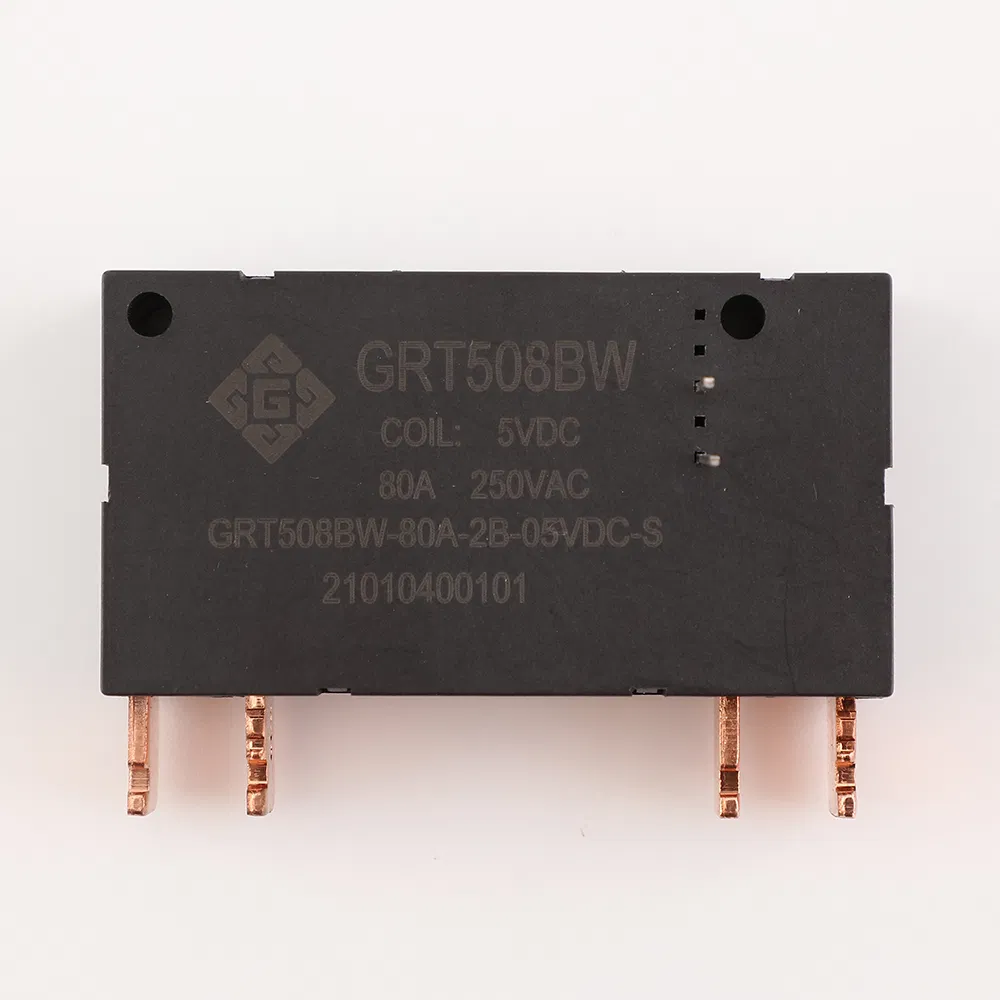
GRT508BW: two-pole, 80 A resistive, fast-connect latching relay with a 55.6 x 30 x 16.5 mm outline.
The 60 A tier: GRT508BV
GRT508BV is the 60 A option, at the lower end of the same GRT508B family rating range, and it inherits the group's single-pole, fast-connect configuration along with the 250 VAC maximum switching voltage, the 5–24 VDC coil range, the 100,000-operation mechanical endurance, the 10,000-operation electrical endurance and the 4 kV coil-to-contact dielectric strength.
The 60 A tier is not a compromise part for buyers who wanted 90 A. It is the correct specification where the meter's continuous current profile, the upstream protection and the load category keep the switching duty comfortably inside the tier. Sizing a relay to a higher rating than the circuit requires adds a dimension the design must absorb without changing the fault behaviour the meter enclosure was designed for. The decision rule is the rated current of the switching duty, not the highest number in the catalogue.
How pulse-driven latching switching changes the specification
Latching relays, also described as bistable relays, hold their contact position with a permanent magnet rather than a continuously energised coil. Manufacturer technical documentation describes the mechanism the same way: the magnetic field generated by a permanent magnet attracts or releases the contacts, so the contact state is retained without continuous coil supply.
In the meter context, the operating mode GRT documents follows from that principle — pulse-driven switching, with the contact state maintained after switching, single- or dual-coil excitation options, and coil voltages from 5 to 24 VDC. The steady-state coil draw is effectively eliminated; the driver must still deliver a defined pulse, and the pulse energy budget becomes a design parameter rather than an afterthought.
Two boundaries belong in the same paragraph. A latching relay is a switching element, not a protective device: the published short-circuit figures of 2500 A/10 ms and 4500 A/10 ms (no explosion) describe a stated withstand window, and they do not convert the relay into an overcurrent protective device. And because the contact state is retained without power, the control system must know the current state before issuing the next pulse — a design obligation that sits in firmware, not in the relay datasheet.
Where each rating tier fits in a metering installation
The GRT metering application data describes the working envelope these relays are documented against: ambient temperature -40 °C to +85 °C, relative humidity 5% to 85% RH non-condensing, altitude up to 2000 m, no corrosive gas or explosive dust in the surroundings, PCB soldering or screw mounting, and resistive load. The matched equipment is a smart electricity meter or energy measurement module, the function is on-off control of meter circuits with low power consumption after latching, and the stated special requirements are high shock and vibration resistance, long mechanical life and low coil power consumption.
- 90 A tier (GRT508BJ, GRT508BG): single-phase meter designs where the disconnect element must carry a service current with margin above the 60 A tier, and where a single-pole topology matches the meter layout.
- 80 A tier (GRT508BW): designs that must switch two poles simultaneously — line and neutral, or two load paths — and can absorb a 55.6 mm body length.
- 60 A tier (GRT508BV): single-phase branch metering, sub-metering and lower-current switching duties where the continuous profile and upstream protection keep the duty inside the tier.
All three tiers share the same fast-connect termination, which means terminal tooling and assembly sequence are common across the shortlist. That commonality is a practical advantage when a product family has to cover more than one meter platform: the same harness or busbar interface can be reused even where the contact tier changes.
Market signals behind the meter relay shortlist
The relay category overall is forecast to grow from USD 11.75 billion in 2026 to USD 15.65 billion by 2031, according to MarketsandMarkets. That figure covers all relay types, including electromechanical, solid-state and latching devices, and it is not a latching-relay market size. Estimates for the same base year differ between research houses — one published estimate places 2024 at USD 10.61 billion against another at USD 10.13 billion — which indicates methodology differences in what is included rather than a disagreement about direction.
Two structural signals matter more to a buyer than the headline number. First, latching relays are an established smart-metering component: Johnson Electric lists bi-stable and latching relays within its smart metering solutions, which confirms application maturity beyond a single supplier. Second, the category is not directly observable in trade statistics. HS 8536 splits relays by voltage — 8536.41 covers relays for voltages not exceeding 60 V, and 8536.49 covers other relays — and there is no separate code for latching relays. Any analysis of import dependence or regional supply structure has to declare that limitation rather than substitute the 8536 total for a latching-relay figure.
The standards layer is where the shortlist connects to procurement risk. Relay compliance is layered rather than single-certificate: generic electromechanical relay safety requirements sit in IEC 61810-1, application requirements for payment metering sit in IEC 62055-31, and horizontal regulation such as Directive 2011/65/EU (RoHS 2) applies to electrical and electronic equipment placed on the EU market. A supplier qualification file therefore has to be assembled from layers, and each layer checked against the destination market.
Limits of this shortlist, and the comparison trap
The most important limitation is that this shortlist cannot rank the four models by cost. No verified unit price, MOQ, tooling charge, lead time or landed-cost data exists in the public record for these models, so any ordering by value would be invented. The shortlist orders by contact tier and configuration because those are documented; commercial ordering has to come from quotations.
A second limitation is model-level resolution. GRT508BJ and GRT508BG share a rating tier and a family datasheet, and the public documentation does not state what separates them. A buyer who needs the difference must request it, not infer it.
A third limitation concerns comparison across brands. Contact ratings from different manufacturers are not comparable until voltage, load category, contact configuration, endurance and test method are normalised. A 90 A figure from one source and a 90 A figure from another can describe different test regimes, and treating them as equivalent is the most common error in relay shortlisting.
Finally, the tier logic itself has a boundary. Choosing 60 A where the duty is 60 A leaves no margin for a load profile that drifts upward; choosing 90 A where the duty is 40 A adds a component whose rating is never exercised. Neither choice is wrong in principle — the point is that the tier decision should be traced to a stated duty, recorded, and re-checked when the meter platform changes.
From shortlist to RFQ: purchasing terms and acceptance criteria
An RFQ built on this shortlist should convert each open parameter into a line item with an acceptance rule attached. The table below is structured that way: the left column is what the buyer specifies, the right column is why the specification changes the answer.
| RFQ item | What to specify | Why it changes the selection |
|---|---|---|
| Contact rating and load definition | Required current at a stated voltage (90 A, 80 A or 60 A tier), AC voltage, load category, expected inrush | A resistive rating does not describe an inductive or capacitive duty; the tier is only valid inside the stated load condition |
| Pole count and contact configuration | Single-pole or two-pole, and the switching topology it must serve | GRT508BW is two-pole; the 90 A and 60 A options are single-pole in family data. Pole count changes the footprint |
| Mounting form and clearance | Fast-connect termination, terminal spacing, available envelope | Published outlines differ: 38 x 30 x 16.5 mm for the single-pole group, 55.6 x 30 x 16.5 mm for the two-pole product |
| Coil specification | Coil voltage within 5–24 VDC, single or dual coil, pulse width and drive energy | Pulse energy is a system design parameter in a latching architecture |
| Endurance requirement | Required mechanical and electrical operations for the duty cycle | Family data states 100,000 mechanical and 10,000 electrical operations; the duty cycle determines which figure governs |
| Short-circuit withstand | Required withstand value and duration | Family and GRT508BW data state 2500 A/10 ms and 4500 A/10 ms (no explosion); confirm against the meter's fault level |
| Dielectric strength | Required coil-to-contact withstand | Documented at 4 kV between coil and contacts across the shortlist |
| Ambient conditions | Temperature range, humidity, altitude, atmosphere | Documented envelope is -40 °C to +85 °C, 5–85% RH non-condensing, altitude ≤2000 m, no corrosive gas or explosive dust |
| Compliance evidence | RoHS declaration or test report, and the certificate behind the stated utilization category | The shortlist cites IEC 62055-31 UC2 for the GRT508B group and IEC 62052-31 UC2 for GRT508BW; the certificate must match the standard number quoted |
| Custom assembly scope | Whether flexible wire, copper strap or integrated shunt is required | GRT documents custom assemblies with these options; scope changes tooling and validation |
| Commercial terms | MOQ, sample quantity, lead time, Incoterms, packaging | None of these are published; they must come from the quotation, not from the catalogue |
Acceptance criteria should be written before samples are ordered, not after they arrive. A practical set for this shortlist covers four gates: dimensional fit against the meter envelope, pulse-drive behaviour at the specified coil voltage and pulse width, contact resistance and dielectric verification on the delivered lot, and document verification in which the certificate number, standard reference and product model match the purchase order. Sample validation is the step where the tier decision is confirmed against the real design — GRT states that 3–5 free samples of standard models are available for testing with the buyer covering freight, and that custom products require separate confirmation.
Outlook
Two developments are likely to keep this shortlist structure stable. The first is the continuing use of latching relays in smart metering, which is documented at manufacturer level and does not depend on a forecast. The second is the standards layer: with IEC 62055-31 defining UC2 through UC4 and IEC 61810-1 setting general safety requirements, buyers are increasingly asked to qualify against a category rather than a general claim, which pushes the evidence requirement down to certificate level.
What may change is the input to the tier decision. As meter platforms add remote disconnect, load profiling and two-pole isolation, pole count and mounting form are likely to filter the shortlist before contact rating does. The 55.6 mm two-pole body against the 38 mm single-pole body already shows how quickly a configuration decision overrides a 10 A difference. Buyers who record their duty definition and acceptance gates once will be able to re-run this shortlist against the next platform without restarting the qualification.
Full product documentation is available in the GRT Relay catalogue (PDF), and company information at en.grtrelay.com.
FAQ
What does the contact rating on a meter latching relay actually cover?
A contact rating states a current the contacts can switch under defined conditions, and the GRT documentation states these as resistive-load ratings at a maximum switching voltage. Separate figures cover mechanical endurance, electrical endurance, short-circuit withstand and dielectric strength. The rating therefore describes a duty envelope, not a general capability, and it is only valid while the load category, voltage and test conditions stay inside that envelope.
How should a buyer choose between 60 A, 80 A, and 90 A meter relay options?
Start from the switching duty: the continuous current the relay must carry, the voltage, the load category and the fault level the meter must withstand. The 60 A, 80 A and 90 A tiers then act as filters rather than preferences. The 90 A tier suits duties that need margin above 60 A in a single-pole layout; the 80 A tier is the two-pole option and is selected when two poles must switch together; the 60 A tier suits duties that remain inside its range with upstream protection unchanged.
Does pole count change the selection more than contact rating does?
It can. GRT508BW is documented as a two-pole product with a 55.6 x 30 x 16.5 mm outline, while the single-pole GRT508B group is documented at 38 x 30 x 16.5 mm. A design that must switch two poles cannot substitute a higher-rated single-pole part, and a design with a fixed envelope may be unable to accept the two-pole body at all. Pole count and mounting form are therefore hard filters, while contact rating within a tier is a margin decision.
Which compliance documents should accompany a meter latching relay order?
The shortlist documentation cites RoHS compliance across the four models, IEC 62055-31 UC2 for the GRT508B group, and IEC 62052-31 UC2 for GRT508BW. Because those are different standard numbers, the qualification file should hold the certificate that matches the standard quoted for the specific model, together with a RoHS declaration or test report. IEC 61810-1 exists as the general safety standard for electromechanical elementary relays and is commonly referenced alongside application standards.
Are samples available before a production order?
GRT states that 3–5 free samples of standard models are available for testing, with the buyer covering freight, and that custom products require separate confirmation. Sample validation is the stage at which the contact tier, pole count, mounting form and pulse-drive behaviour are confirmed against the actual meter design rather than against a datasheet.
What belongs in an RFQ for a latching relay shortlist?
An RFQ for this shortlist should specify the contact rating with its load definition, pole count and contact configuration, mounting form and available envelope, coil voltage and pulse parameters, endurance requirement, short-circuit withstand requirement, dielectric strength, ambient conditions, and the compliance documents required with their standard references. Commercial terms — MOQ, lead time, Incoterms and custom assembly scope — should be requested as separate line items, because none of them appear in published product documentation.
¿Tiene preguntas o necesita más detalles?
Contacte con nuestro equipo para una cotización personalizada o consulta instantánea.
Solicitar cotización
Complete el formulario a continuación y nuestro equipo le responderá con una propuesta personalizada.
Chat directo de WhatsApp
¿Prefiere chatear en tiempo real? Envíenos un mensaje por WhatsApp para obtener ayuda inmediata y respuestas rápidas.
- Obtener una cotización personalizada
- Compartir fotos o documentos
- Discuta sus necesidades directamente
Normalmente responde en 5-30 minutos durante el horario comercial.