
Inline 3D Scanning on Smart Manufacturing Lines
Inline 3D Scanning on Smart Manufacturing Lines
Inline 3D scanning can bring dimensional data closer to the production process, but a scanner alone does not make an inspection line-ready. The inspection task, part characteristics, robotic coverage, software workflow and the intended production decision all need to fit together. The SHINING 3D RobotScan Series is an automation solution combining a high-accuracy 3D scanner with an industrial robot or collaborative robot. Its stated role includes automated optical measurement for mass-production inspection; the right configuration depends on the part and inspection requirements.
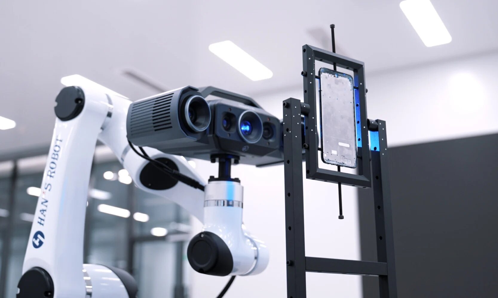
For a quality team researching a 3D scanner for quality control, the practical question is not simply whether a system can capture a 3D scan. It is whether the measurement approach can cover the relevant features, fit the part and cell constraints, and produce results the inspection process can use. RobotScan is most directly relevant when the planned task is automated inspection of small or medium-sized components, rather than an assumption that every handheld or portable 3D scanning task should be moved onto a robot.
What inline 3D scanning means for quality control
Inline 3D scanning places automated 3D measurement within, or in coordination with, a production workflow. Instead of treating every inspection as a separate manual scan, a configured system can use a robot to present a scanner to a part along a programmed measurement path. The resulting 3D data can be used in an inspection workflow that includes data processing, alignment, CAD comparison, deviation analysis, dimensional measurement and reporting.
That description is a workflow model, not a claim that every installation automatically inspects every part, makes a pass-or-fail decision in real time, or communicates with a factory control system. Those outcomes depend on the selected equipment, software, integration and acceptance criteria. The supplied RobotScan information describes an automated optical 3D measurement solution for mass-production inspection, but does not specify a universal cycle time, line connection, reject mechanism or inspection rate.
For manufacturers, this distinction matters. An automated capture path can make repeated measurement more structured, but it does not by itself define which dimensions matter, how tolerances are applied, or what action follows a deviation. Before calling a cell “inline,” the team should agree whether the intended scope is a dedicated automated inspection station, a sampled check near the line, or a more integrated production-stage inspection process.
Where the RobotScan Series fits
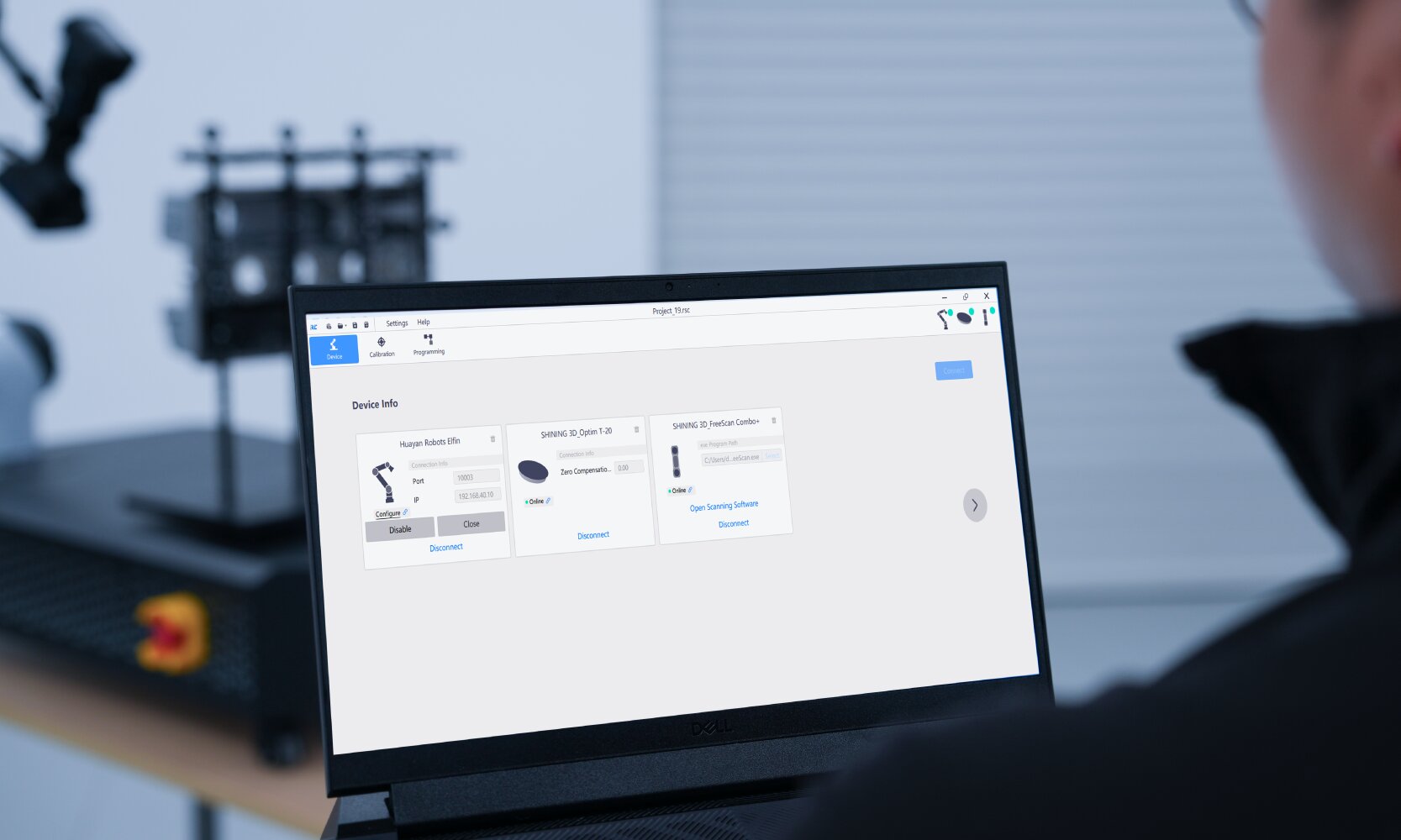
The SHINING 3D RobotScan Series combines a scanner, a robot or collaborative robot, and associated automation components. The listed series models are RobotScan Q12, RobotScan UE Pro2 and RobotScan Combo+. The system configuration can be customized: the robotic arm brand, SHINING 3D scanner, turntable, fixtures, and control and inspection software can be tailored to application requirements.
This makes RobotScan a candidate for a production task where repeatable, programmed scanner movement is appropriate and the part can be presented within the configured measurement area. The listed series parameters specify measurable object size of up to 500 mm, turntable load capacity of up to 20 kg, a robot working radius of 800 mm and system weight of 70 kg. These are stated parameters for the series information supplied; they should not be treated as a complete cell layout or as proof that an individual part fits without checking its orientation, fixture, access and scanning path.
The buyer implication is straightforward: check the actual workpiece envelope and fixture together, not just the nominal part dimensions. A part may be within the stated size limit yet still present access challenges if important surfaces are hidden, if the required viewing angles are obstructed, or if the fixture prevents the scanner from reaching inspection areas. Confirming these details during application planning is more useful than assuming a robot can inspect every surface simply because the system is automated.
How the three RobotScan configurations map to parts
The scanner choice is a question of part geometry, surface and inspection purpose. The supplied product information describes different roles for RobotScan Q12, RobotScan UE Pro2 and RobotScan Combo+; it does not establish one model as the universal choice for all inline quality control.
| Configuration | Supported fit description | Questions to resolve |
|---|---|---|
| RobotScan Q12 | Fringe projection; described for small parts with complex surfaces, geometries or sharp edges. Examples include airfoils, brackets, connectors, gears, housings and electronic components. The series material identifies it for automated optical measurement in mass-production inspection. | Are the features to inspect visible to the scanner along the planned path? Does the part’s size and fixture suit the configured measurement setup? |
| RobotScan UE Pro2 | Handheld blue laser scanning technology with material adaptability for black, shiny and reflective surfaces. Described for small and medium sheet metal parts, casting housings, machined parts and mold components. Wireless and wired connectivity are listed for flexible on-site integration. | Does the actual surface and geometry call for this scanner option? Which connection and integration arrangement is required in the cell? |
| RobotScan Combo+ | Hybrid light source for varied part types and batch inspection of small-to-medium castings and machined parts. Examples include mixed-size covers, trim pieces, assemblies and medium castings. | Does the production mix justify a hybrid configuration, and can the planned inspection sequence accommodate the different part types? |
These descriptions give engineers a starting point for matching scanning method to inspection task. They do not supply a complete part-by-part accuracy, cycle-time or coverage guarantee. In particular, a listed application example is not evidence that a specific production line has already been deployed or validated. For a production decision, request the configuration-specific measurement information and verify it against the features and tolerances that matter to the buyer.
From 3D scan to an inspection decision
A useful inline inspection concept connects data capture to a defined quality question. The general 3D inspection sequence is to acquire 3D data, process and align it, compare it with CAD or another approved reference, evaluate dimensions or geometric tolerances, and prepare results for review and documentation. A 3D inspection scanner for quality assurance is therefore only one part of the system: inspection software, alignment method, reference data, measurement plan and report requirements also matter.
- Define the inspection purpose. Identify whether the cell is intended for first article inspection, recurring production checks, dimensional deviation analysis or another specified task. Name the features and acceptance criteria before selecting a scan path.
- Check part presentation. Review the part envelope, fixture, turntable requirements, load and robot reach. For RobotScan, compare the actual setup with the stated maximum measurable object size of 500 mm, turntable load of up to 20 kg and 800 mm robot working radius.
- Choose the scanner option against the part. Consider whether complex detail, dark or reflective surfaces, or mixed part types are relevant to the stated Q12, UE Pro2 or Combo+ configuration descriptions. Verify the actual component and surface rather than relying on a broad category label.
- Plan acquisition and analysis together. Confirm which surfaces are captured, how the scan is aligned to the reference, and whether the inspection software supports the required dimensions, GD&T evaluation, deviation analysis and reporting. The provided general workflow describes these analysis stages, but does not confirm every feature for every RobotScan configuration.
- Validate the intended production use. Establish acceptance criteria for repeatability, measurement results, data handling and the response to an out-of-tolerance result. Confirm the production interface and operating sequence with the relevant integration team; these details are not specified in the supplied RobotScan series facts.
This sequence also helps distinguish a 3D scanner for automated in-line inspection from a portable scanner used for on-site or shop-floor inspection. Both approaches capture 3D data, but they address different operating models. RobotScan is described as a robotic automation solution. A handheld or portable scanner is operated by a person and can be brought to a part or measurement location. The latter may be a better practical starting point when parts are large, varied, difficult to move or not yet suited to a fixed robotic path. The RobotScan material does not claim that its listed configuration replaces portable inspection in those situations.
Application boundaries: small parts, mixed production and shop-floor checks
For small components with complex geometry, RobotScan Q12 is described as a fit to investigate when automated detailed measurement is the goal. The supplied examples include connectors, gears, housings and electronic components. This is relevant to a 3D scanner for electronic parts quality control when the specific component fits the system’s stated size and setup boundaries. It does not establish a blanket fit for every electronic part or every tolerance requirement.
For sheet metal, cast housings, machined parts and mold components, RobotScan UE Pro2’s stated blue laser and material adaptability make it an option to assess where dark, shiny or reflective surfaces are part of the inspection challenge. That is a configuration description, not proof that every finish can be scanned without preparation or that every feature will be measurable. Run a representative application check using the actual part, surface condition and required dimensions.
RobotScan Combo+ is described for manufacturers inspecting diverse small-to-medium castings and machined parts, including mixed-size covers, trim pieces, assemblies and medium castings. Its hybrid light source is positioned around versatility across part types. For a production team considering batch inspection, the central decision is whether the product mix and inspection plan can be handled by a common configured process or require different setups. The supplied information does not specify changeover time or throughput for mixed batches, so those should be validated rather than assumed.
For shopfloor inspection, the relevant question may instead be whether an automated cell is practical at the place where parts are produced. A robot-based setup requires a defined working area, part presentation and integration plan. If the task is an occasional check on a large asset, an in-place repair inspection or a measurement on a component that cannot be brought to the cell, a handheld approach may align better with the location of the work. SHINING 3D’s broader product information includes portable scanners for on-site inspection, but their use should not be conflated with the RobotScan Series’ automated configuration.
What “inline” does—and does not—establish
The term “inline” can refer to different levels of production integration. A robot that captures a part at a dedicated inspection station is automated, but the available facts do not establish that the station is synchronized with a conveyor, performs a check on every unit, or sends a disposition command to production equipment. Likewise, a 3D scan and a color deviation map do not by themselves define the product’s pass/fail rule. Those features require a specified software workflow, comparison reference and decision criteria.
For that reason, manufacturers should separate three questions during a feasibility review. First, can the proposed scanner and robot capture the required geometry under the actual part and fixture conditions? Second, can the inspection process evaluate the necessary dimensions against approved references and tolerances? Third, can the resulting measurement and decision be integrated into the intended quality process? The first is a measurement and access question; the second is an analysis question; the third is a production-system question. Evidence for one does not automatically answer the others.
This distinction is especially important when considering claims about full-surface coverage or non-destructive testing. 3D scanning captures surface geometry, and the supplied knowledge material describes non-contact inspection. It does not establish that a surface scan detects internal defects or replaces other forms of testing. For a non-destructive testing 3D scanner query, the intended test must be defined precisely: a geometric surface measurement should not be represented as an internal-material inspection without supporting evidence.
Buyer checks before evaluating an automated inspection cell
A focused review can determine whether RobotScan merits a closer application evaluation without assuming a production outcome. Buyers can ask:
- Part and fixture: Is the part within the stated measurable size and turntable load limits, and can the required faces be reached within the listed robot working radius?
- Inspection characteristics: Which dimensions, surfaces, edges, holes or geometric tolerances must be evaluated, and what reference data defines acceptable results?
- Scanner fit: Which RobotScan model is proposed, and what evidence supports its use with the actual geometry and surface condition?
- System scope: Which robot, turntable, fixtures, control software and inspection software are included in the proposed configuration, and which are tailored or optional?
- Process performance: What cycle time and inspection frequency have been demonstrated for the specific part and workflow? These values are not given in the provided series information.
- Production integration: What data, signals or reports must pass between the inspection station and other production or quality systems? Confirm the required interfaces and responsibilities explicitly.
- Verification evidence: What acceptance procedure and measurement evidence will be used to establish that the configured cell meets the application’s requirements?
These checks keep a procurement discussion tied to the actual line and quality plan. They also prevent a common category error: treating a scanner’s technical capability, a robot’s programmed movement and a validated production inspection process as interchangeable evidence.
How RobotScan fits in the broader 3D QC workflow
RobotScan occupies the automated-cell part of the 3D quality-control landscape described in the supplied information. Its distinguishing context is the combination of scanner and robot for automated optical measurement, with three scanner options aimed at different part characteristics and a customizable system configuration. For production teams considering repeatable measurement of suitable small or medium components, it gives a concrete automation route to evaluate.
It is not, on the available evidence, a universal answer for every 3D scanner for deviation inspection, first article inspection, mold wear inspection or shop-floor measurement requirement. The fit depends on the component’s size and access, the inspection features, the selected scanner, the cell configuration and the software and integration scope. Nor does the presence of an automated system alone establish faster inspection, lower cost or improved quality outcomes; those results require application-specific evidence.
In practical terms, begin with the measurement task, not the robot. Define what must be measured, identify the parts and production conditions, and then check whether the RobotScan configuration can capture and analyze the needed data within its stated limits. Where those conditions align, the series can be considered as an automated 3D scanning option for manufacturing QC. Where the work is mobile, unusually large or not yet defined as a repeatable cell task, portable on-site inspection may remain the more relevant workflow to assess.
FAQ: Inline 3D scanning and RobotScan
What is the SHINING 3D RobotScan Series?
The SHINING 3D RobotScan Series is an automation solution combining a high-accuracy 3D scanner with an industrial robot or collaborative robot. The listed models are RobotScan Q12, RobotScan UE Pro2 and RobotScan Combo+. The series information describes it as an automated optical measurement solution for mass-production inspection.
Which parts are described for RobotScan inspection?
The supplied examples include small complex parts such as airfoils, brackets, connectors, gears, housings and electronic components for RobotScan Q12; small and medium sheet metal parts, casting housings, machined parts and mold components for RobotScan UE Pro2; and small-to-medium castings, machined parts, covers, trim pieces, assemblies and medium castings for RobotScan Combo+. These examples do not confirm suitability for every part in those categories.
Can RobotScan be used for automated in-line inspection?
The RobotScan Series is described as a robotic automation solution for automated optical measurement and mass-production inspection. The supplied information does not specify that every deployment is synchronized with a production line, inspects every unit, or makes real-time pass/fail decisions. Those functions depend on the configured system, software and integration requirements.
What should be checked before selecting a RobotScan configuration?
Check the actual part and fixture against the stated series parameters: measurable object size up to 500 mm, turntable load capacity up to 20 kg and robot working radius of 800 mm. Also verify scanner fit against the part’s geometry and surface, required inspection dimensions, software workflow, system configuration and production interfaces. The supplied series information does not provide a universal cycle time or application-specific acceptance result.
¿Tiene preguntas o necesita más detalles?
Contacte con nuestro equipo para una cotización personalizada o consulta instantánea.
Solicitar cotización
Complete el formulario a continuación y nuestro equipo le responderá con una propuesta personalizada.
Chat directo de WhatsApp
¿Prefiere chatear en tiempo real? Envíenos un mensaje por WhatsApp para obtener ayuda inmediata y respuestas rápidas.
- Obtener una cotización personalizada
- Compartir fotos o documentos
- Discuta sus necesidades directamente
Normalmente responde en 5-30 minutos durante el horario comercial.