
Inline 3D Scanning on Smart Lines: RobotScan in QC
Inline 3D Scanning on Smart Lines: RobotScan in QC
Inline 3D scanning is most relevant when manufacturers need a repeatable way to capture part geometry as part of a production inspection workflow—not simply a faster way to collect scan data. SHINING 3D’s RobotScan Series is an automation solution combining a high-accuracy 3D scanner with an industrial or collaborative robot. Its role in quality control is to support automated optical measurement of parts, with the scanner configuration selected according to component geometry and inspection needs. The available product information describes a configurable inspection system; it does not establish a particular production-line installation, conveyor connection, takt time, or plant-level result.
For smart manufacturing teams assessing a 3D scanner for quality control, that distinction matters. A robot-mounted scanner can automate data capture, but a useful inspection process also depends on part presentation, scan coverage, alignment, comparison logic, tolerances, and how results are handled. RobotScan should therefore be considered as an automated measurement cell or inspection component whose fit must be validated against the actual line and quality plan.
What inline 3D inspection adds to a QC process
A 3D inspection workflow captures the surface geometry of a physical part and can compare the resulting scan data with a CAD reference. That comparison can be used to examine dimensional deviations and evaluate specified features. Depending on the inspection software and defined plan, the workflow can include data acquisition, processing and alignment, CAD comparison, deviation analysis, dimensional measurement, GD&T evaluation, and reporting.
This full-field view addresses a different measurement need from checking only a limited set of points. A scan can represent the measured surface as a 3D dataset, which can help engineers examine shape differences across a part rather than relying solely on selected dimensions. It does not, by itself, prove that every surface or characteristic is inspected to a required tolerance. Coverage, measurement strategy, alignment, scanner performance, and acceptance criteria still need to be defined for each application.
In a production setting, the potential value of automating inspection is procedural consistency: a programmed scan path and defined analysis process can help standardize repeated data capture. Whether an automated inspection cell can operate within a particular line’s timing, handling, and quality requirements must be established for that installation. The supplied RobotScan information does not specify a universal cycle time or guarantee a line-speed match.
Where the RobotScan Series fits
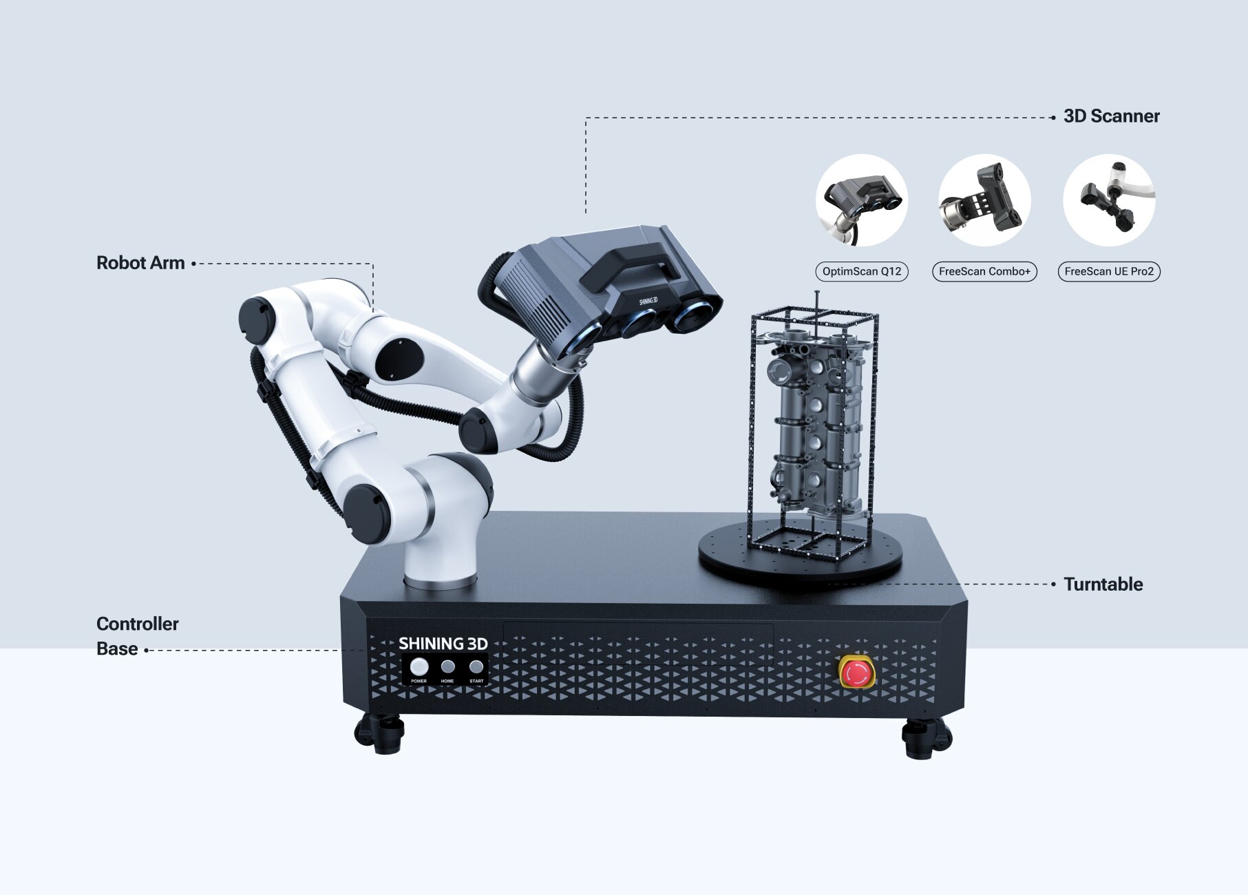
SHINING 3D describes RobotScan as a customizable automation solution combining a high-accuracy 3D scanner, an industrial robot, and a collaborative robot. Its listed system components can be tailored to application requirements and may include different robotic-arm brands, a SHINING 3D scanner, a turntable, fixtures, and control and inspection software. This makes the series relevant to manufacturers evaluating an automated 3D inspection setup, while leaving the exact system design dependent on the selected application and configuration.
The product unit names three configurations: RobotScan Q12, RobotScan UE Pro2, and RobotScan Combo+. The supplied descriptions connect each to a different scanning approach and part profile. These are not interchangeable labels for one fixed configuration. Selecting among them requires matching the scanner’s stated strengths to the actual workpiece, required detail, surface characteristics, and inspection procedure.
| RobotScan configuration | Described scanning approach | Stated fit in the supplied product information | What to confirm for QC |
|---|---|---|---|
| RobotScan Q12 | Fringe projection technology | Small parts with complex surfaces, geometries, or sharp edges; examples include airfoils, brackets, connectors, gears, housings, and electronic components. | Whether the part size, surface details, required measurement characteristics, and planned coverage suit the configured system. |
| RobotScan UE Pro2 | Handheld blue laser scanning technology in the automation solution | Small and medium sheet-metal parts, casting housings, machined parts, and mold components; the description notes adaptability to black, shiny, and reflective surfaces. | The material and surface behavior of the actual part, scan access, and required coverage under the intended setup. |
| RobotScan Combo+ | Hybrid light source | Batch inspection of small-to-medium castings and machined parts, as well as mixed-size components such as covers, trim pieces, assemblies, and medium castings. | Whether one configured workflow can address the specific part mix and the inspection characteristics required for each part. |
The table summarizes application descriptions, not comparative test results. It does not establish that one configuration is more accurate, faster, or more suitable than another in every situation. A selection should be based on the part and measurement task, with the system configuration and inspection plan reviewed together.
From robot motion to an inspection result
An automated 3D scanner captures geometry; inspection software and a defined measurement plan turn that geometry into quality information. In a typical digital inspection sequence described in the supplied workflow material, the operator or automated system first acquires 3D data. The data is then processed and aligned before comparison with a CAD reference. Deviation analysis, dimensional inspection, or GD&T evaluation can follow, with results organized into an inspection report when the workflow supports reporting.
- Define the inspection target. Identify the part, CAD reference, features, dimensions, and tolerances that the quality plan requires. A general 3D scan is not a substitute for deciding which characteristics determine acceptance.
- Plan the scan and part presentation. Determine how the part will be positioned, which surfaces and features must be captured, and whether the selected scanner and robot arrangement can reach them. The part’s geometry and the cell’s fixtures affect what the scan can cover.
- Acquire and prepare scan data. Capture the part geometry using the selected RobotScan configuration, then process and align the data for analysis. The method of alignment should be suitable for the inspection purpose rather than chosen only for visual convenience.
- Compare and evaluate. Compare the scan with the CAD reference or defined measurement criteria. Use deviation maps and dimensional or GD&T tools where they are part of the selected software workflow and inspection plan.
- Review and document. Confirm that the outputs address the required characteristics and that the report contains the information needed for review. A report is only as meaningful as its measurement plan, references, and acceptance rules.
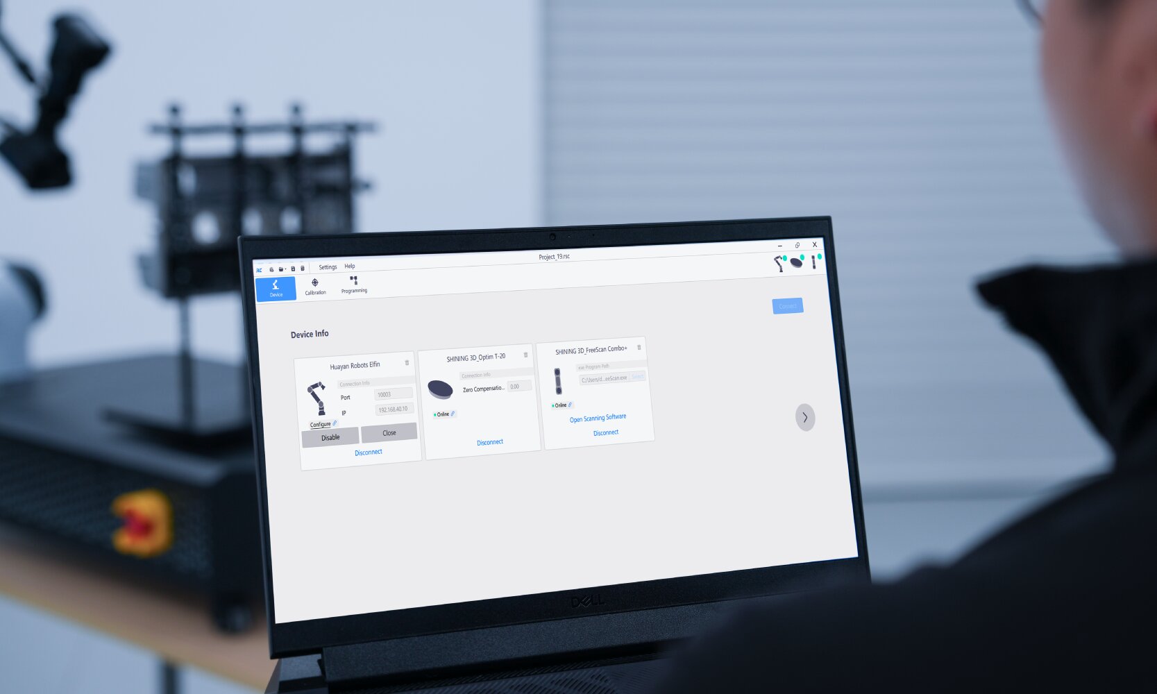
This sequence helps explain why the term automated inspection 3D scanner should refer to more than a robot moving a sensor. The useful system boundary includes scanner, robot, part holding, control, inspection software, and the quality process that interprets results. The RobotScan product information supports configurable system components, but it does not state that every listed component, software connection, or reporting function is included in every offer. Those details should be confirmed for the exact configuration under evaluation.
Applications: match the part and inspection objective
RobotScan’s stated application range includes automotive, energy and heavy industry, engineering machinery and other transportation, marine, civil aviation, mold manufacturing, and MRO. The product descriptions give more specific examples that can help a manufacturing team frame its evaluation:
- Small, detailed components: RobotScan Q12 is described for complex geometries and fine-detail components such as connectors, gears, brackets, housings, and electronic components. That profile makes it a candidate to assess for detailed 3D inspection where the feature geometry and required measurement plan align with the configured system.
- Sheet-metal and machined workpieces: RobotScan UE Pro2 is described for small and medium sheet-metal parts, casting housings, machining parts, and mold components. Its blue laser scanning approach is stated to have strong material adaptability on black, shiny, and reflective surfaces. The exact surface condition and inspection requirement still need to be checked on representative parts.
- Mixed component batches: RobotScan Combo+ is described for small-to-medium castings and machined parts, with examples including covers, trim pieces, assemblies, and medium castings. Its hybrid light source is presented as a way to address different part types in a configurable automated scanning solution; that description does not establish that a single setup will meet every inspection requirement across a mixed batch.
- Manufacturing and maintenance contexts: The series’ stated industries include heavy machinery, marine, mold manufacturing, and MRO. A manufacturer or maintenance team can use those categories to identify a potential application, then verify whether the particular geometry, access, environment, and quality criteria are supported by the chosen configuration.
Related search phrases such as 3D scanner for automated in-line inspection, 3D scanner for shopfloor inspection, 3D scanner for mold inspection, 3D scanner for sheet metal inspection, and 3D scanner for electronic parts quality control describe distinct buyer questions, not proof of an installation or outcome. For example, an in-line inspection requirement involves process integration and timing questions in addition to scan capability. Mold or sheet-metal inspection adds geometry and feature questions. Electronic-part quality control may place greater emphasis on small features and measurement detail. The supplied RobotScan descriptions help identify possible configuration fit, but do not specify a universal line interface or acceptance result for these applications.
Interpreting system limits and configuration data
The RobotScan product unit lists several system parameters: measurable object size of no more than 500 mm, turntable load capacity of no more than 20 kg, robot working radius of 800 mm, and weight of 70 kg. These are listed as RobotScan Series parameters, rather than as separate figures for each named scanner configuration. They should not be treated as a complete installation envelope or as proof that every workpiece within those limits can be inspected.
Before applying those values to a line concept, clarify what the stated measurable object size represents for the proposed setup and how the object will be oriented and presented. Check the required scan coverage, robot reach, fixture and turntable arrangement, and the relationship between part dimensions and the scanner’s working path. The turntable load figure should be assessed alongside the actual part and fixture load, not treated as an unlimited capacity statement. The available information does not provide a general conveyor specification, floor-space drawing, cycle-time value, or line-control interface.
This boundary is especially important for a 3D scanner for GD&T. The scanner’s ability to capture 3D data is only one part of a tolerance evaluation. The inspection plan must define the relevant datums, features, dimensions, tolerances, and alignment approach, and the selected software configuration must support the required analysis. The product information identifies control and inspection software as configurable components, but does not establish that a specific GD&T module or report format is standard in every RobotScan system.
Buyer checks before considering an inline cell
A buyer can make an early RobotScan evaluation more useful by documenting the measurement task instead of beginning with a general claim of automation. The following checks keep the review tied to the quality requirement:
- Part and feature definition: Record the part family, relevant dimensions, material and surface characteristics, and the specific features or surfaces to inspect. Identify whether the task concerns a first article, repeated production parts, or another defined inspection stage.
- Measurement requirement: State the tolerances and measurement characteristics that matter. Separate the need for broad surface deviation information from the need to evaluate specific dimensions or GD&T characteristics.
- Coverage and accessibility: Map the surfaces, edges, pockets, and other features that must be measured. Review whether robot movement, part orientation, fixtures, and the selected scanner can provide the required access.
- Configuration match: Use the stated RobotScan Q12, UE Pro2, and Combo+ application distinctions as starting points for discussion, not as a substitute for checking the actual part and inspection plan. Confirm which scanner and components are included in the proposed configuration.
- Workflow and software: Confirm how scan data will be acquired, aligned, compared, and reported, and which inspection functions and software are part of the configuration. Review how results will be interpreted in the buyer’s existing quality process.
- Line requirements: Define the required inspection position, material flow, timing, operator interaction, and any required communication with other equipment. The supplied product description does not specify a universal line-control interface or throughput figure, so those requirements need configuration-specific confirmation.
- Validation evidence: Agree how the proposed setup will be evaluated using representative parts and the buyer’s own acceptance criteria. Distinguish a scanner specification from evidence that a complete cell meets the requirements of a particular inspection task.
These checks are not a claim that every RobotScan deployment needs the same layout or validation procedure. They are a way to connect the stated equipment capabilities to a real manufacturing decision. In particular, a specification for one component should not be mistaken for a performance result for the entire automated inspection process.
What RobotScan’s role means for smart manufacturing
RobotScan fits the smart-manufacturing QC conversation as a configurable automated optical measurement solution for parts that align with its stated size and application descriptions. The key distinction is between automated scanning and validated in-line inspection. The former describes an automated data-capture approach. The latter also depends on the specific cell design, production integration, measurement plan, and verified ability to meet the buyer’s defined requirements.
For early-stage research, the practical starting point is to classify the inspection task: fine-detail small parts, sheet-metal or machined components, or mixed casting and machined-part batches. Then match the stated RobotScan configuration to the part type and define what evidence is needed to confirm the fit. This keeps a search for a 3D inspection scanner for quality assurance grounded in the actual inspection question rather than in broad claims about automation.
SHINING 3D’s product information positions the RobotScan Series around a combination of robotic handling and optical 3D scanning, with configurable system components and application-specific scanner options. For manufacturing teams, its relevance depends on whether that combination can be configured to capture the required geometry and deliver inspection outputs that fit their QC process. No general claim about production-line speed, achieved defect detection, or plant-wide improvement follows from the supplied specifications alone.
Frequently asked questions
What is inline 3D scanning in manufacturing quality control?
Inline 3D scanning is the use of 3D data capture within or alongside a production inspection workflow. The scan can be processed and compared with CAD data or defined measurement criteria to examine geometry and dimensional deviations. Whether a particular setup is truly integrated into a production line depends on its configured cell, process timing, part handling, and required interfaces.
Where does the RobotScan Series fit in an automated QC process?
The RobotScan Series is described as an automation solution combining a high-accuracy 3D scanner with an industrial or collaborative robot. Its listed configurations are intended for different part profiles, including detailed small components, sheet-metal and machined parts, and mixed small-to-medium castings. The product information does not establish that every configuration is already deployed on a specific line or meets a universal cycle-time requirement.
Which RobotScan configuration is described for small, detailed components?
RobotScan Q12 is described for small-sized parts with complex surfaces, geometries, or sharp edges, with examples including airfoils, brackets, connectors, gears, housings, and electronic components. The specific part size, required detail, measurement characteristics, and final system configuration still need to be checked for the inspection task.
What should a manufacturer verify before selecting an automated 3D scanner?
Define the part and measurement requirements, then verify scan coverage, access, part presentation, scanner configuration, software functions, reporting needs, and integration requirements. For RobotScan, the listed parameters include a measurable object size of no more than 500 mm, turntable load capacity of no more than 20 kg, robot working radius of 800 mm, and system weight of 70 kg. Confirm how those system-level parameters apply to the proposed configuration; they do not alone establish inspection suitability or production-line performance.
For background on SHINING 3D’s 3D digitizing portfolio, see the company brochure.
¿Tiene preguntas o necesita más detalles?
Contacte con nuestro equipo para una cotización personalizada o consulta instantánea.
Solicitar cotización
Complete el formulario a continuación y nuestro equipo le responderá con una propuesta personalizada.
Chat directo de WhatsApp
¿Prefiere chatear en tiempo real? Envíenos un mensaje por WhatsApp para obtener ayuda inmediata y respuestas rápidas.
- Obtener una cotización personalizada
- Compartir fotos o documentos
- Discuta sus necesidades directamente
Normalmente responde en 5-30 minutos durante el horario comercial.