
Inline 3D Scanning for Smart Manufacturing QC
Inline 3D Scanning for Smart Manufacturing QC
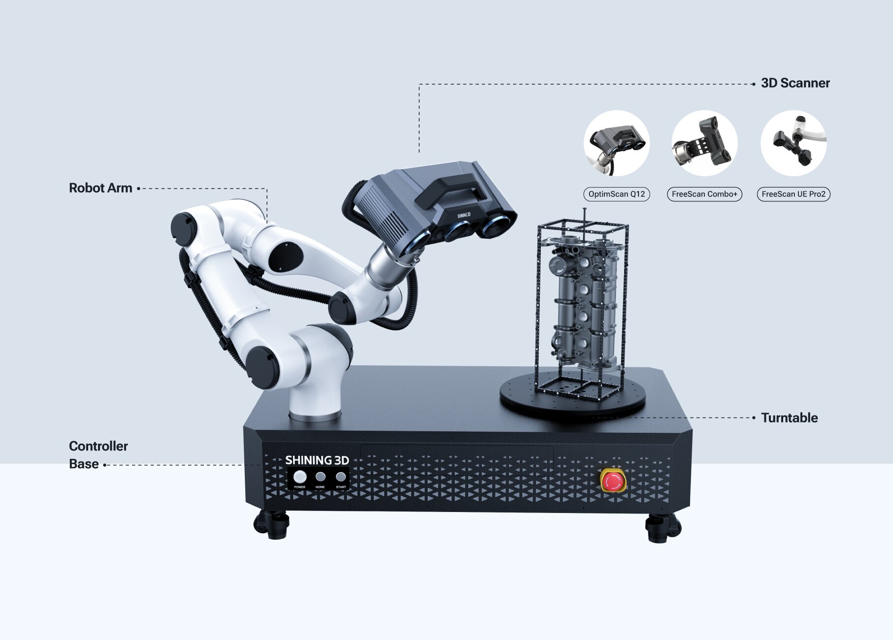
Inline 3D scanning can place dimensional inspection closer to the production process, but the right setup depends on the part, measurement plan, and desired level of automation. SHINING 3D’s RobotScan Series is an automation solution combining a high-accuracy 3D scanner with an industrial robot or collaborative robot. Its role in quality control is as a configurable robotic inspection system for defined workpieces—not as a guarantee that every existing production line can be converted to fully automatic inspection without engineering and workflow integration.
For manufacturers assessing a 3D scanner for quality control, that distinction matters. A robotic cell can be considered when parts are repeatable enough to support a planned scan path and handling arrangement. A handheld or portable 3D scanner, by contrast, can be more appropriate when inspection must move between stations, parts, or hard-to-reach locations. RobotScan focuses on the robotic, repeatable-capture side of that decision. The supplied product information lists RobotScan Q12, RobotScan UE Pro2, and RobotScan Combo+ as series models, with the scanner and configuration selected according to the inspection task.
What “inline” means for a 3D inspection scanner
Inline inspection generally places measurement within or alongside the manufacturing sequence, rather than treating every scan as a separate laboratory activity. In a proposed setup, a part may be positioned for robotic scanning, the scanner captures surface data, and inspection software evaluates the data against the relevant reference or measurement requirements. Whether this can operate at a particular line position depends on the actual automation design, part presentation, scan coverage, inspection cycle, and integration requirements.
The RobotScan specification describes an automation solution, but the supplied material does not establish a universal conveyor arrangement, cycle time, automatic reject mechanism, or connection protocol for every production line. Those details should not be assumed from the word “inline.” A buyer evaluating a 3D scanner for automated in-line inspection should therefore distinguish the scanner-and-robot measurement cell from the wider production system that may be needed to feed parts, manage results, and determine the next process step.
This is especially important in smart manufacturing, where a digital measurement result is useful only if it is tied to a defined inspection task. The task might be to compare captured geometry with CAD, check selected dimensions, or review surface deviation. The intended output and decision rule should be agreed before deciding that a robotized scan is a complete production-control solution.
Where RobotScan Series fits in manufacturing QC
RobotScan is a fit to evaluate for manufacturers whose inspection requirements align with the series’ stated object-size and system parameters and whose workpieces can be presented to a robot-based scanning setup. The product information identifies applications across automotive, energy and heavy industry, engineering machinery and other transportation, marine, civil aviation, mold manufacturing, and MRO. These are application categories, not proof of a specific customer deployment or a guarantee of suitability for every part in those industries.
The choice among the listed scanner options is linked to workpiece geometry and surface characteristics. RobotScan Q12 uses fringe projection technology and is described for small parts with complex surfaces, geometries, or sharp edges, including examples such as airfoils, brackets, connectors, gears, housings, and electronic components. The product description presents it as an automated optical measurement solution for mass-production inspection. This makes it a candidate to assess where detailed capture of small, feature-rich components is central to the inspection plan.
RobotScan UE Pro2 uses handheld blue laser scanning technology and is described as having strong material adaptability for black, shiny, and reflective surfaces. Its stated fit includes small and medium-sized sheet metal parts, casting housings, machined parts, and mold components. The product information also notes wired and wireless connectivity for on-site integration. For a 3D scanner for sheet metal inspection or mold inspection, the relevant question is not simply whether the scanner is robotic: the team should confirm that the intended surface, feature access, measurement range, and inspection criteria are addressed in the proposed configuration.
RobotScan Combo+ uses a hybrid light source and is described for varied part types and batch inspection of small-to-medium-sized castings and machined parts. The stated examples include covers, trim pieces, assemblies, and medium castings. Its fit is therefore framed around a mixture of part types where a hybrid light source is relevant, rather than a single universal scanning mode for every material and geometry.
How the robotic 3D scanning workflow supports QC
A useful way to assess an automated inspection 3D scanner is to follow the data from physical part to quality decision. The supplied quality-control workflow describes acquisition, data processing and alignment, CAD comparison and deviation analysis, dimensional inspection and GD&T evaluation, followed by reporting. RobotScan provides the robotic 3D capture component; the inspection task still needs suitable software, reference data, and a clear interpretation of results.
- Define the inspection question. Identify the part, the features or surfaces to evaluate, the relevant CAD or measurement reference, and the acceptance criteria used by the quality team. A 3D scan is not itself a pass/fail decision unless the inspection plan defines how its measurements will be judged.
- Plan part presentation and scan coverage. Check whether the workpiece is within the listed measurable object size and whether the robot can reach the required surfaces with the chosen fixture and configuration. RobotScan lists a robot working radius of 800 mm and a turntable load capacity of up to 20 kg. These are system parameters to verify against the actual cell layout and part load.
- Capture and prepare 3D data. The scanner acquires surface geometry. Processing and alignment prepare the scan for the comparison task. Coverage, alignment strategy, and data quality are relevant because a missing or poorly aligned region can limit what the later analysis can establish.
- Compare and evaluate. Inspection software can compare scanned data with CAD references, visualize deviations, and support dimensional or GD&T evaluation where the selected software and workflow provide those functions. A color map or deviation display is evidence for review, not a substitute for agreed tolerances and evaluation rules.
- Review and record results. A report can organize measurement and deviation information for further review. The production team should determine how inspection outcomes are recorded and used in its own quality process; the supplied RobotScan information does not specify a universal line-control or reject function.
Choosing between robotic inline scanning and portable inspection
A 3D scanner for shopfloor inspection does not have to be a robot-mounted system. A portable scanner can support onsite measurement when the operator needs to move to a part, inspect different areas, or work away from a fixed cell. A robotic configuration is more relevant when a defined, repeatable scan path and part presentation are practical. The choice is about workflow fit, not a general claim that one form factor is superior.
| Inspection need | RobotScan Series consideration | What to verify |
|---|---|---|
| Repeated capture of a defined component family | A robotic scanner configuration may support a planned scan routine for recurring inspection. | Part positioning, scan coverage, robot reach, inspection criteria, and the required production sequence. |
| Small parts with complex geometry or sharp edges | RobotScan Q12 is described for small, detailed components and complex surfaces. | Actual part size, required detail, reference data, and the measurement task. |
| Dark, shiny, or reflective small-to-medium parts | RobotScan UE Pro2 is described as having material adaptability for these surfaces. | Test the actual material and surface condition in the intended configuration; do not infer performance on every finish. |
| Mixed small-to-medium castings and machined parts | RobotScan Combo+ is described for varied part types and batch inspection. | Part mix, required scan modes, fixture and turntable limits, and the inspection plan. |
| Changing locations or irregular access needs | A fixed robotic cell may not be the most practical arrangement for every onsite task. | Consider whether a handheld or portable scanning workflow better matches operator access and part movement. |
The comparison also clarifies why the phrase “3D scanner for quality control” covers several different tasks. A robot-mounted scanner addresses automation of data capture. A portable scanner emphasizes mobility and access. A fixed optical scanner may be considered for a different workpiece size or measurement environment. This article focuses on RobotScan’s robotic application; it does not treat those other equipment types as equivalent or rank them against RobotScan.
Application examples and fit boundaries
For automotive manufacturing, the supplied application material includes vehicle bodies and automotive components, with possible inspection contexts such as stamping dies, engine and powertrain components, and manufacturing quality control. RobotScan Q12’s listed examples of gears, housings, brackets, and electronic components can help frame a small-part use case, while the UE Pro2 description specifically includes sheet metal parts. The exact line application still depends on part dimensions, access, surface, and the required measurement outputs.
For electronics quality control, the available scenario information describes dimensional measurement of housings and components, CAD comparison, deviation analysis, flatness inspection, and deformation or warpage analysis. It identifies in-line automation inspection as a special requirement for that scenario, while listing desktop scanning as the operation mode and separate equipment models. This supports the relevance of 3D measurement to electronic-part QC, but it does not establish that every electronics component or scenario is a RobotScan application. RobotScan Q12’s product information does include electronic components among fine-detail examples; the buyer should still confirm the specific workpiece and configuration.
For mold manufacturing and MRO, RobotScan UE Pro2’s stated fit includes mold components, and the series’ applicable industries include mold manufacturing and MRO. That makes the family relevant to evaluation for selected inspection tasks. It does not, by itself, establish a dedicated mold-wear measurement result, a repair outcome, or a completed deployment. If the task is to inspect wear or a repaired component, define the reference condition and comparison method so that the scan supports a meaningful decision.
Large structures require particular attention to scope. The supplied RobotScan Series specification lists a measurable object size of up to 500 mm, so it should not be presented as a system for scanning an entire ship hull or large construction machine in one setup. The wider corpus describes separate handheld and dynamic tracking products for large-object scanning, but those are not the RobotScan Series. Keeping that distinction prevents an appealing “shopfloor 3D scanning” use case from becoming an unsupported capability claim.
Practical evaluation criteria before adding a cell
Before selecting a 3D inspection scanner for quality assurance, engineering, metrology, and production teams can use a short technical review to establish fit. First, describe the actual component envelope and weight; compare these with the RobotScan Series parameters rather than relying on the broad industry label. The stated measurable object size is up to 500 mm and the turntable load capacity is up to 20 kg. Confirm whether those limits apply to the proposed fixture and part arrangement.
Second, map the surfaces and features that matter. If the decision concerns a GD&T characteristic, a hole or slot, a complex edge, or a broad surface deviation, specify what must be captured and how the result will be evaluated. The scanner’s stated model-level use cases can guide questions, but an application description is not a substitute for validating the actual part and measurement plan.
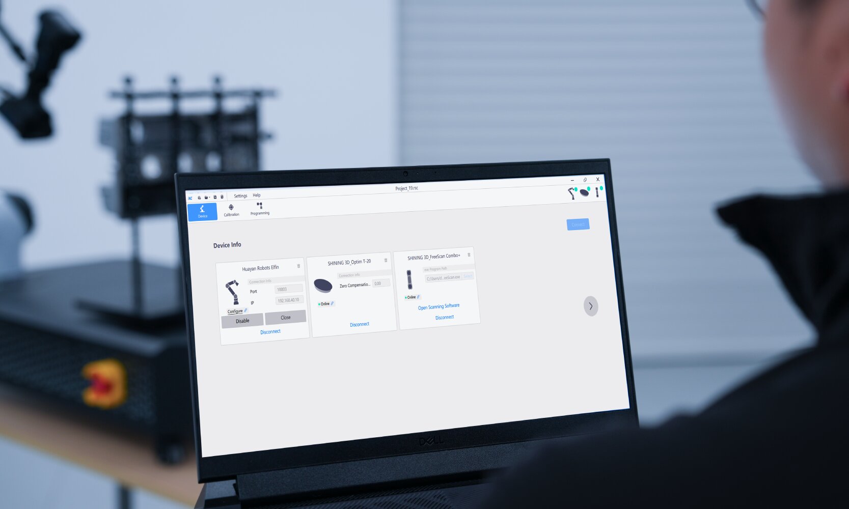
Third, consider the cell around the scanner. RobotScan configurations can be customized, and the supplied product information says components such as different robotic-arm brands, SHINING 3D scanners, turntables, fixtures, and control and inspection software can be tailored to application requirements. Customization means the configuration may be adapted; it does not establish that a particular integration is included by default. Document the selected robot, fixture, software, and required interfaces for the intended setup.
Finally, evaluate the whole inspection workflow rather than one headline specification. Acquisition speed alone does not describe total inspection time: setup, part handling, scan coverage, processing, evaluation, and result review all influence the task. Establish how often the part is presented, which data must be retained, and who reviews exceptions. This gives a more grounded basis for deciding whether robotic inline 3D scanning is appropriate than assuming automation automatically shortens every inspection cycle.
Where the RobotScan Series fits
RobotScan Series fits the smart-manufacturing QC discussion as a configurable robotic 3D scanning solution for defined, small-to-medium inspection tasks. Its listed models map to different part and surface considerations: Q12 for detailed complex small components, UE Pro2 for small and medium parts including black, shiny, or reflective surfaces, and Combo+ for varied small-to-medium castings and machined parts. The supplied system parameters and application descriptions give buyers a starting point for technical evaluation, not a blanket promise of line readiness.
For a 3D scanner for automated in-line inspection, the decisive next step is to check the real part, scan coverage, system limits, robot reach, cell layout, software workflow, and inspection decision rules together. Where parts are mobile, oversized relative to the stated range, or require changing access points, a portable or other scanning approach may be a better topic for evaluation. SHINING 3D, a 3D vision technology company established in 2004, publishes its company information at SHINING 3D.
Frequently asked questions
What is RobotScan Series used for in quality control?
RobotScan Series is an automation solution combining a high-accuracy 3D scanner with an industrial or collaborative robot. Its supplied application information covers manufacturing and inspection contexts including automotive, engineering machinery, marine, energy and heavy industry, mold manufacturing, and MRO. Suitability depends on the part, configuration, and defined inspection task.
Can RobotScan be used for automated in-line inspection?
RobotScan is described as an automation solution for optical 3D measurement, and the product information includes mass-production inspection among the Q12 applications. The supplied information does not define a universal conveyor interface, cycle time, reject function, or line protocol. Those elements need to be confirmed for the specific production cell.
What part size and load limits are listed for RobotScan Series?
The supplied RobotScan Series parameters list a measurable object size of up to 500 mm, turntable load capacity of up to 20 kg, and robot working radius of 800 mm. Check the selected configuration and actual fixture-and-part arrangement against these limits before designing a cell.
How do the RobotScan Q12, UE Pro2, and Combo+ differ in their stated applications?
RobotScan Q12 is described for small parts with complex surfaces, geometries, or sharp edges. RobotScan UE Pro2 is described for small and medium sheet metal, casting housing, machining, and mold components, including black, shiny, and reflective surfaces. RobotScan Combo+ uses a hybrid light source and is described for varied small-to-medium castings and machined parts. These descriptions guide evaluation; they do not replace a check using the actual workpiece and inspection requirements.
Is RobotScan the same as a portable handheld 3D scanner for onsite inspection?
No. RobotScan Series is described as an automation solution with a scanner and industrial or collaborative robot. Handheld and portable scanning refer to operator-carried scanning workflows. A RobotScan configuration may include a handheld scanner model, but the series-level system is positioned as robotic automation; choose the workflow according to access, repeatability, part presentation, and inspection needs.
¿Tiene preguntas o necesita más detalles?
Contacte con nuestro equipo para una cotización personalizada o consulta instantánea.
Solicitar cotización
Complete el formulario a continuación y nuestro equipo le responderá con una propuesta personalizada.
Chat directo de WhatsApp
¿Prefiere chatear en tiempo real? Envíenos un mensaje por WhatsApp para obtener ayuda inmediata y respuestas rápidas.
- Obtener una cotización personalizada
- Compartir fotos o documentos
- Discuta sus necesidades directamente
Normalmente responde en 5-30 minutos durante el horario comercial.