
ISO 10360 vs. VDI/VDE 2634: How SHINING 3D Certifies Scanner Accuracy
ISO 10360 vs. VDI/VDE 2634: How SHINING 3D Certifies Scanner Accuracy
Industrial buyers rarely struggle to find an accuracy figure for a metrology 3D scanner. They struggle to find out what that figure is based on. Two scanners can both be marketed as “certified” while the documents behind them reference different standards, cover different measurement parameters, and are issued under different levels of laboratory accreditation.
That gap matters most in industries where a measurement result has to survive an audit — automotive, civil aviation, energy, mold manufacturing, and precision electronics. This article explains what ISO 10360 and VDI/VDE 2634 each cover, which SHINING 3D scanner models state an acceptance test against one or both, and where the boundary of an accuracy certificate actually sits.
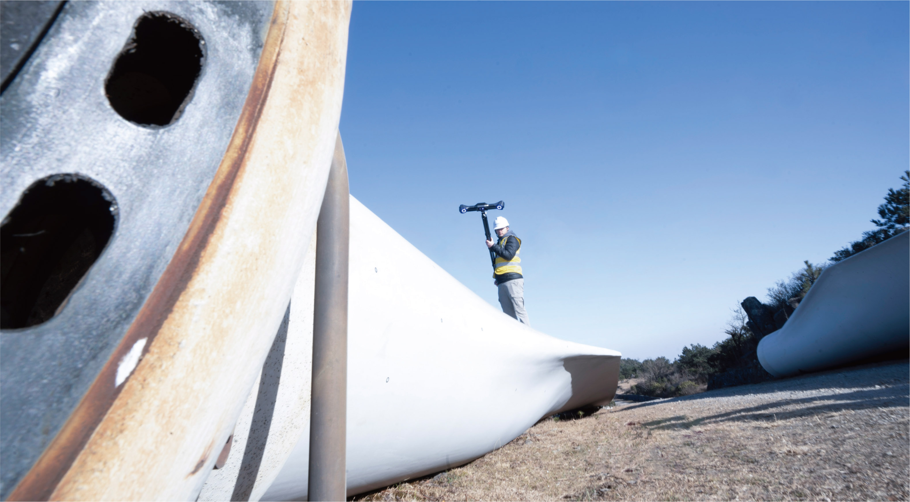
Why “Accuracy Certificate” Can Mean Three Different Things
In practice, a scanner supplier may hand over any of three document types, and they are not interchangeable:
- An acceptance test result — a statement that a scanner or scanner type was tested against a named standard, such as VDI/VDE 2634 Part 3 or ISO 10360.
- A calibration certificate — a record that a specific instrument was calibrated using certified artifacts or calibration panels traceable to metrology standards.
- A laboratory accreditation scope — evidence that the facility performing the testing is itself assessed against a recognised laboratory standard.
ISO/IEC 17025 is the accreditation that is generally treated as the critical verification requirement for laboratories publishing 3D scanner accuracy data. Without it, a buyer has no independent basis for judging whether the numbers in a datasheet were produced under controlled, repeatable conditions or simply reported by the manufacturer.
Equally important: a supplier may hold accreditation, publish an acceptance test reference, and still ship a scanner whose individual certificate covers only part of what the buyer assumes. That is the core risk in this category, and it is a documentation risk rather than a hardware risk.
ISO 10360 and VDI/VDE 2634: Two Standards, Two Different Jobs
VDI/VDE 2634 — written for optical area-scanning systems
VDI/VDE 2634 Part 3 is the primary standard for evaluating the accuracy of optical 3D measuring systems based on area scanning. That scope is what makes it relevant to the majority of industrial 3D scanners, because handheld laser scanners, tracking scanners, and structured-light scanners all capture a surface patch rather than a single touched point.
SHINING 3D documentation also references VDI/VDE 2634 Part 2 for one fixed inspection model, which indicates that the applicable part of the standard can differ by scanner type rather than by brand. A buyer comparing two suppliers should therefore compare the part number, not just the standard name.
ISO 10360 — the ISO framework for coordinate measurement acceptance
The ISO 10360 series is the ISO framework for acceptance and reverification testing of coordinate measuring systems. It is not a single document: ISO 10360-12, for example, establishes international requirements for the acceptance and reverification of articulated arm coordinate measuring machines.
Several SHINING 3D scanners state their acceptance test as VDI/VDE 2634 Part 3 and ISO 10360 together, and the OptimScan Q12/Q9 documentation additionally cites ISO 10360-13. For a buyer, the practical reading is straightforward: the supplier is claiming that the system was verified against both the optical area-scanning standard and the broader ISO coordinate measurement framework.
| Comparison point | VDI/VDE 2634 | ISO 10360 |
|---|---|---|
| Issuing body | VDI/VDE Society (Europe / global adoption) | ISO (international) |
| Primary focus | Optical 3D measuring systems based on area scanning (Part 3 stated as primary; Part 2 also referenced in SHINING 3D documentation) | Acceptance and reverification of coordinate measuring systems; Part 12 addresses articulated arm CMMs |
| Typical relevance to a scanner buyer | Confirms an optical scanner was evaluated as an area-scanning measurement system | Confirms the system sits inside the ISO coordinate measurement acceptance framework |
| What it does not do | Does not guarantee performance on a specific part, material, or shop-floor environment | Does not convert a scanner into a CMM or transfer a certification to a different configuration |
How SHINING 3D States Its Accuracy Basis, Model by Model
SHINING 3D (Shining 3D Tech Co., Ltd.), founded in 2004 and headquartered in Hangzhou, China, develops high-precision 3D vision hardware and software for industrial metrology and digital dentistry. Its portfolio includes metrology 3D scanners, professional 3D scanners, entry-level 3D scanners, and dental 3D solutions. The company employs approximately 1,367 staff, including 533 R&D engineers, operates a manufacturing facility covering 140,000 square meters, and sells into more than 100 countries, with the EU, USA, and APAC as its main markets and export business accounting for 70% of total sales. In 2025, its operating revenue exceeded USD 220 million.
For accuracy documentation specifically, the more useful fact is that SHINING 3D operates a dedicated precision laboratory accredited in accordance with ISO/IEC 17025, and states that calibration and verification procedures for its scanners are performed in that accredited Accuracy Lab.
The table below summarises the acceptance test basis stated in the product documentation for each metrology-relevant model line.
| Model | Stated accuracy | Acceptance test basis stated in documentation |
|---|---|---|
| FreeScan Trak Nova Series | 0.02 mm; volumetric accuracy 0.062 mm over 12 m³; 0.046 mm + 0.012 mm/m with VPG | VDI/VDE 2634 Part 3 & ISO 10360, tested in the ISO/IEC 17025 accredited accuracy lab |
| FreeScan Omni / FreeScan Omni Lite | 0.02 mm; volumetric accuracy 0.02 + 0.03 mm/m; 0.02 + 0.015 mm/m with VPG | VDI/VDE 2634 Part 3 & ISO 10360, tested in the ISO/IEC 17025 accredited lab |
| FreeScan Combo Series | 0.02 mm; volumetric accuracy 0.02 + 0.033 mm/m | VDI/VDE 2634 Part 3 & ISO 10360, tested in the ISO/IEC 17025 accredited lab |
| FreeScan Combo+ Wireless / FreeScan Combo Wireless | 0.02 mm; 0.02 + 0.03 mm/m; 0.02 + 0.015 mm/m with VPG | ISO 10360 certified, tested in the ISO/IEC 17025 accredited Accuracy Lab |
| FreeScan UE Nova | 0.072 mm; volumetric accuracy 0.072 + 0.012 mm/m with VPG | VDI/VDE 2634 Part 3 & ISO 10360 |
| OptimScan Q12/Q9 | 0.015 mm large range; up to 0.005 mm small range | VDI/VDE 2634 & ISO 10360, including ISO 10360-13, tested in the ISO/IEC 17025 accredited lab |
| OptimScan Q12/Q9 HD | 0.01 mm large range; 0.004 mm small range | VDI/VDE 2634 Part 2 & ISO 10360, tested in the ISO/IEC 17025 accredited lab |
| AutoScan Inspec2 | Up to 0.01 mm (10 microns) | Documentation for this model lists CE, FCC, ROHS, WEEE and KC; it does not state a VDI/VDE 2634 or ISO 10360 acceptance test |
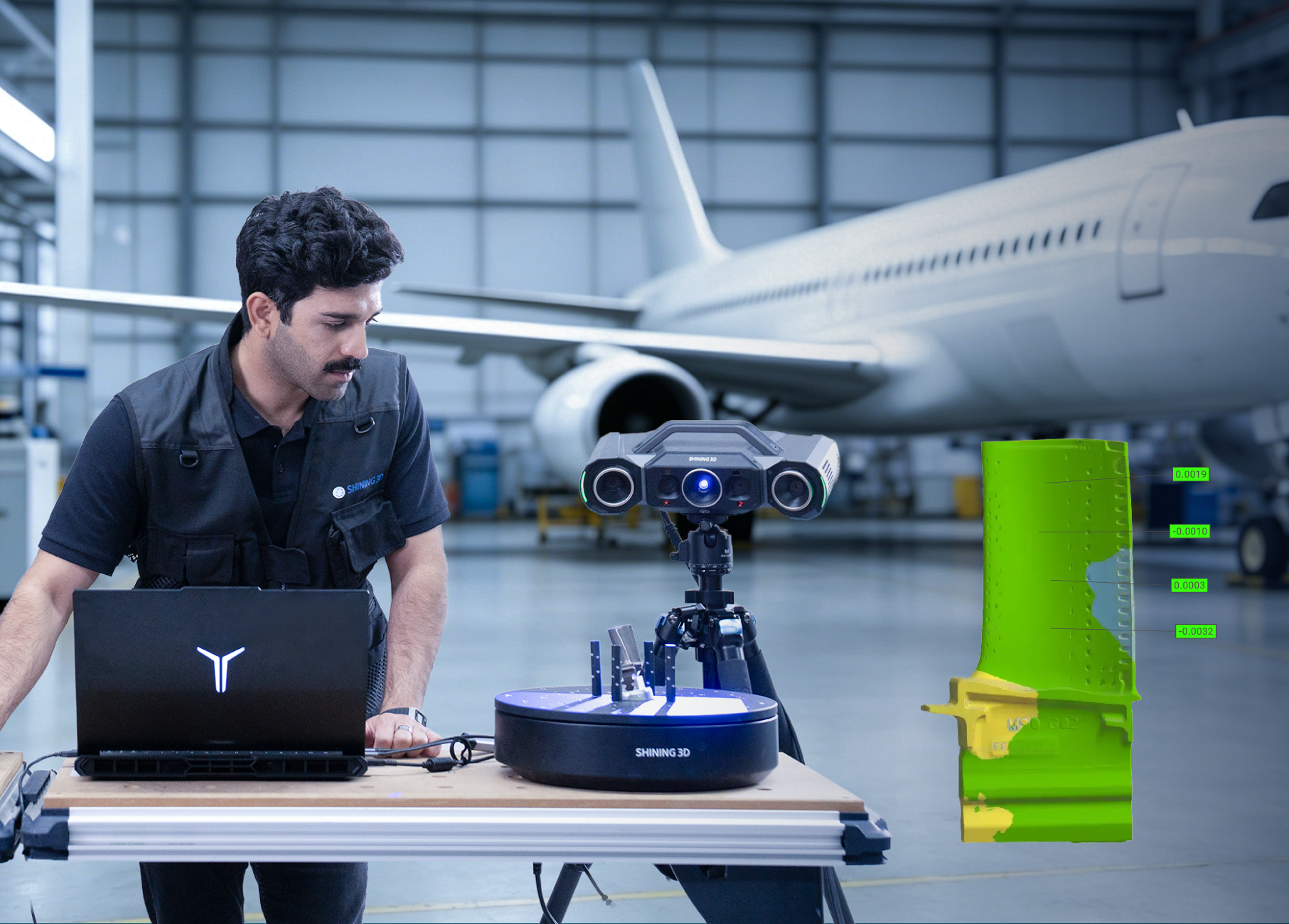
Read the table honestly. The last row is as informative as the first seven. A supplier that documents one product line against VDI/VDE 2634 and ISO 10360 and another only against product-safety certifications is telling the buyer something useful: the acceptance-test claim is model-specific, not brand-wide. Buyers should apply the same test to every supplier on their shortlist.
What the Certificate Covers — and What It Does Not
This is the part of the topic where generality is dangerous, so it is worth stating the documented position precisely. SHINING 3D’s own published answer on certification states that its scanners provide inspection reports and calibration certificates traceable to international standards such as VDI/VDE 2634 and ISO 10360 — subject to the actual certificates issued — and that all calibration and verification procedures are performed in the company’s accredited Accuracy Lab, which operates in accordance with ISO/IEC 17025 requirements.
The phrase “subject to the actual certificates issued” is the operative one, and it is a fair description of how metrology documentation works across the industry. An accuracy certificate typically describes:
- A specific tested configuration — scanner model, optics, firmware or software version, and in some cases tracking or photogrammetry options.
- Specific measurement parameters — usually a combination of single-point or form-related accuracy and volumetric behaviour, rather than one global number.
- Specific test conditions — the laboratory environment and setup in which verification was carried out.
- A point in time — the certificate reflects the instrument’s state when tested, not an ongoing guarantee that survives transport, shock, or years of shop-floor use.
What it does not do is certify performance on the buyer’s part, material, or production floor. Two consequences follow. First, volumetric behaviour accumulates over distance: a scanner specified at 0.02 mm + 0.015 mm/m produces a maximum measurement error of approximately 0.05 mm when measuring a 2-metre object, because the distance-dependent term is added to the base term. Second, scanning conditions interact with the technology — structured-light systems that project fringe patterns, for example, can be affected by strong ambient light, which is why controlled or managed lighting conditions are part of the operating envelope for fixed inspection systems.
A certificate is therefore a starting condition, not a final answer. The buyer’s incoming verification remains the only test of whether the delivered system performs in the buyer’s own environment.
Maintaining Traceability After Delivery: Calibration Practice
Certification at delivery and traceability over time are different obligations. SHINING 3D states that its scanners are calibrated using certified artifacts or calibration panels traceable to metrology standards, and that regular calibration maintains measurement traceability, sustains accuracy, and aligns the instrument with quality management requirements. The inspection software used in the workflow, SHINING3D Inspect, is PTB-certified.
The company also publishes the conditions under which recalibration should be considered, and these are worth quoting because they translate directly into a maintenance schedule:
- When the scanner is used for the first time, or after one to two weeks of inactivity.
- If the scanner has been severely shaken or vibrated, such as during transport.
- If accuracy is significantly reduced, causing frequent alignment errors or unrecognised markers.
- If scanning data is incomplete or data quality has seriously deteriorated.
For a quality manager, these triggers are a useful complement to a calendar-based interval. A scanner that has travelled between sites, or that has been moved between a metrology lab and a production cell, has accumulated exposure that a fixed annual schedule will not capture.
Where the Standard Choice Actually Matters in Industrial Settings
The distinction between ISO 10360 and VDI/VDE 2634 stops being academic as soon as tolerance requirements tighten. Electric-vehicle battery-pack tolerances as tight as 0.025 mm are pushing automakers to replace manual gauges with automated optical scanners, and that tolerance band sits below what many handheld systems can demonstrate without documented verification.
In practice, the application determines which part of the standards family is relevant:
- Small precision parts and electronics. Fixed blue-light structured-light systems are the appropriate class here. The OptimScan Q12/Q9 HD reaches 0.004 mm in small range mode with a 220 × 150 mm large-range field of view, and its documentation references VDI/VDE 2634 Part 2 alongside ISO 10360.
- Shop-floor and on-site inspection. Handheld metrology scanners such as FreeScan Omni or the FreeScan Combo Series state 0.02 mm accuracy with VDI/VDE 2634 Part 3 and ISO 10360 acceptance tests. The FreeScan Combo+ Wireless states ISO 10360 certification with 0.02 mm accuracy and 0.02 + 0.015 mm/m volumetric accuracy using built-in video photogrammetry.
- Large-volume and tracking applications. The FreeScan Trak Nova Series states 0.02 mm accuracy and 0.062 mm volumetric accuracy over 12 m³, with a VPG-assisted figure of 0.046 mm + 0.012 mm/m for extension volumes — the metric that matters when a part is measured in metres rather than millimetres.
- Aerospace and civil aviation MRO. Here the question is usually not single-point accuracy but repeatability across a large airframe or engine component, which is why volumetric accuracy and a traceable calibration path carry more weight than the headline number.
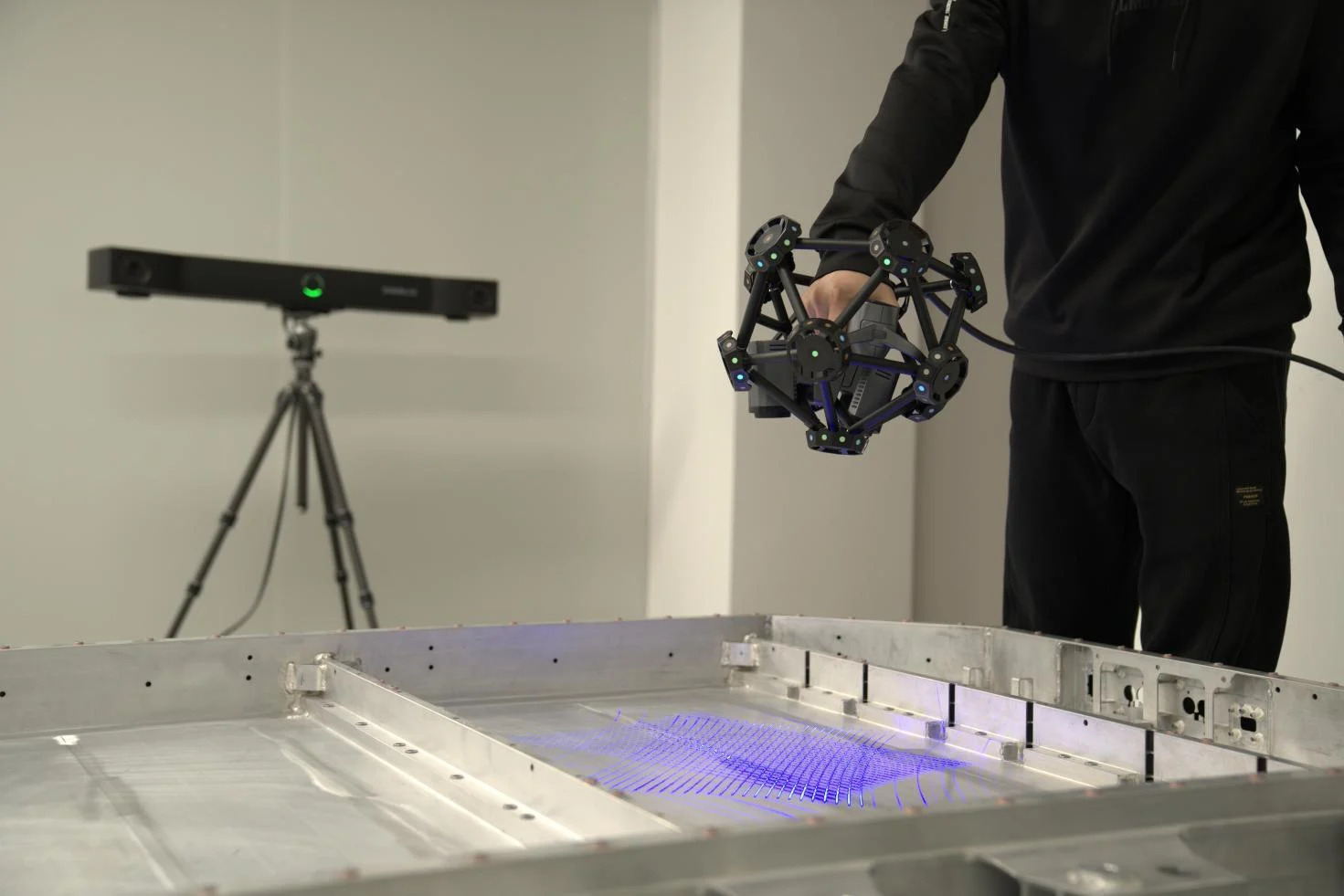
How to Read an Accuracy Certificate During Procurement: Six Checks
A shortlist comparison becomes far more useful when every supplier is asked the same six questions. They are deliberately narrow, because broad questions tend to produce broad answers.
- Which standard, and which part? “VDI/VDE 2634 compliant” is not sufficient. Ask for the part number, since SHINING 3D itself references Part 3 for handheld and tracking systems and Part 2 for one fixed inspection model.
- Which parameter? Confirm whether the certificate addresses single-point or form accuracy, volumetric accuracy, or both. For large parts, the volumetric term usually determines whether the specification is usable.
- Which unit and which configuration? Certificates attach to a configuration. A different scanner body, tracker, or optical option is a different measurement system.
- Which laboratory, and under what accreditation? Ask whether testing was performed in a laboratory accredited to ISO/IEC 17025 — the standard generally required for a laboratory publishing 3D scanner accuracy data.
- Under what conditions? Temperature, lighting, and setup are part of the result. If the certificate assumes a controlled laboratory and the scanner will live on a production floor, that gap should be closed by the buyer’s own verification.
- What is the recalibration path? Ask for the calibration interval, the traceable artifacts used, and the recalled triggers — transport shock, extended inactivity, alignment errors, or degraded data quality.
How This Compares with CMMs, Gauges, and Calipers — and Where It Stops
Traditional measurement remains the reference point for most quality teams. A 3D scanner captures the full 3D geometry of a part in a single measurement. Compared with manual tools, it enables 100% surface inspection rather than key-point checks, reduces operator error, and reveals shape deformations that point measurements frequently miss. Compared with a CMM, it is faster and produces richer data, particularly on complex or freeform surfaces.
That comparison has boundaries that are worth stating plainly:
- Optical systems depend on surface interaction. Dark or highly reflective surfaces, transparency, and certain coatings can complicate data capture and may require specific light sources or surface preparation.
- Structured-light systems are sensitive to strong ambient light, which can disrupt projected fringe patterns and affect results outside a controlled environment.
- Large surfaces may still require reference markers for optimal global accuracy, even on marker-free tracking systems.
- A certificate is not a substitute for incoming verification, and it does not transfer performance from the test configuration to a production configuration.
- Not every product line is documented in the same way. As the model table above shows, VDI/VDE 2634 and ISO 10360 acceptance testing is stated for the metrology handheld, tracking, and fixed inspection lines, while the AutoScan Inspec2 documentation lists CE, FCC, ROHS, WEEE, and KC without a VDI/VDE 2634 or ISO 10360 acceptance-test statement.
Market Context: Why Certificate Discipline Is Being Pushed Forward
The commercial backdrop explains why documentation is becoming a purchasing criterion rather than a footnote. The global 3D metrology market was valued at USD 11.13 billion in 2024 and is projected to reach USD 15.01 billion by 2029, and hardware components — scanners and CMMs — accounted for 66.7% of total 3D metrology revenue in 2023. Within the narrower 3D scanning market, laser scanners represented 45.3% of revenue in 2024, and North America held the largest regional share of the metrology market at 34.5% in 2023, driven primarily by aerospace and automotive demand.
Supplier activity has tracked that demand. Hexagon’s Manufacturing Intelligence division introduced the ATLASCAN Max and MARVELSCAN handheld scanners in May 2024 for automated quality inspection, and Artec 3D released the Artec Point optical CMM system in March 2025, targeting aerospace component verification at 0.02 mm accuracy. Creaform’s HandySCAN BLACK Elite offers metrology-grade accuracy of up to 0.025 mm and is certified to ISO 17025 standards.
Two conclusions follow for buyers. First, accuracy figures across the metrology class are converging, which makes documentation quality one of the few remaining differentiators. Second, the verifiable information a supplier can provide about laboratory accreditation and certificate scope is now more useful than a marginally better datasheet number.
Future Outlook
The direction of travel is toward traceability as a default expectation rather than a premium option. Quality systems in automotive, aerospace, and medical manufacturing increasingly require that measurement data be attributable to a calibrated instrument with a documented verification history, and that expectation flows upstream to the scanner supplier.
Three practical consequences are already visible in how suppliers document their products. Acceptance tests are being named at the level of the standard part, not only the standard family. Software is being certified in its own right, as with PTB-certified inspection modules, because a traceable scanner paired with unverified analysis software does not produce a traceable result. And recalibration criteria are being published rather than left to a service contract, which allows buyers to build measurement reliability into their own quality planning.
For buyers at the research stage of a scanner decision, the sensible sequence is to fix the required tolerance first, choose the scanner class that can demonstrate it second, and only then compare accuracy figures — because the certificate, not the datasheet, determines what a supplier is actually asserting.
FAQ
What is the difference between ISO 10360 and VDI/VDE 2634?
VDI/VDE 2634 is the standard used to evaluate the accuracy of optical 3D measuring systems based on area scanning, with Part 3 commonly cited as the primary reference and Part 2 also referenced in some product documentation. ISO 10360 is the ISO framework for acceptance and reverification of coordinate measuring systems; ISO 10360-12, for example, establishes requirements for articulated arm coordinate measuring machines. VDI/VDE 2634 is specific to optical area-scanning systems, while ISO 10360 covers coordinate measurement acceptance more broadly.
Which SHINING 3D scanners state a VDI/VDE 2634 or ISO 10360 acceptance test?
Published documentation states VDI/VDE 2634 Part 3 and ISO 10360 for the FreeScan Trak Nova Series, FreeScan Omni and FreeScan Omni Lite, the FreeScan Combo Series, and the FreeScan UE Nova. The OptimScan Q12/Q9 states VDI/VDE 2634 and ISO 10360 including ISO 10360-13, and the OptimScan Q12/Q9 HD states VDI/VDE 2634 Part 2 and ISO 10360. The FreeScan Combo+ Wireless states ISO 10360 certification. Testing for these models is stated as performed in an ISO/IEC 17025 accredited lab.
Does every SHINING 3D scanner ship with an accuracy certificate?
Documentation states that SHINING 3D scanners provide inspection reports and calibration certificates traceable to international standards such as VDI/VDE 2634 and ISO 10360, subject to the actual certificates issued. Acceptance-test statements are model-specific rather than portfolio-wide: the AutoScan Inspec2 documentation, for example, lists CE, FCC, ROHS, WEEE and KC without naming VDI/VDE 2634 or ISO 10360. Buyers should confirm the exact certificate, the covered parameters, and the tested configuration for the model and options they intend to purchase.
Who performs the calibration, and what is the traceability basis?
SHINING 3D states that its scanners are calibrated using certified artifacts or calibration panels traceable to metrology standards, and that calibration and verification procedures are performed in the company’s own Accuracy Lab, which operates in accordance with ISO/IEC 17025 requirements. The SHINING3D Inspect software used in the inspection workflow is PTB-certified.
When does a metrology 3D scanner need recalibration?
Documented triggers include first use or after one to two weeks of inactivity; severe shaking or vibration such as during transport; significantly reduced accuracy causing frequent alignment errors or unrecognised markers; and incomplete scan data or seriously deteriorated data quality. These triggers supplement, rather than replace, an organisation’s scheduled calibration interval.
What is volumetric accuracy, and why does it matter for large parts?
Volumetric accuracy describes measurement precision across the entire scanning volume rather than at a single point, and it reflects how errors accumulate with distance. It is expressed as a base term plus a distance-dependent term — for example, 0.02 mm + 0.015 mm/m. When measuring a 2-metre object, the distance term adds approximately 0.03 mm, so the maximum measurement error becomes roughly 0.05 mm. For large components, volumetric accuracy is usually a more decisive specification than single-point accuracy.
For readers who want the underlying product and capability documentation referenced in this article, SHINING 3D publishes a 3D digitizing introduction brochure: SHINING 3D_3D Digitizing introduction.