
ISO 10360 & VDI/VDE 2634 Compliance for QC 3D Scanners
Independent Industry Reference — Metrology & Quality Control
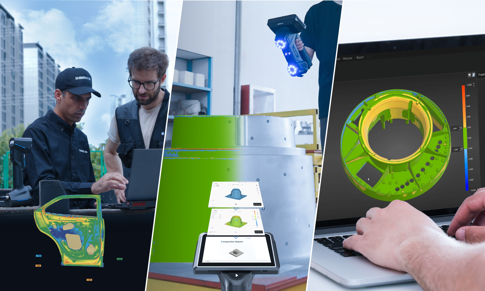
Full-field dimensional inspection with a metrology-grade 3D scanner. The data is only as usable as the traceability behind the instrument that produced it.
A quality department does not buy a 3D scanner for the scan. It buys a measurement that an auditor, an OEM customer, or a certification body will accept. That is why ISO 10360 and VDI/VDE 2634 carry more weight at the purchase decision than the accuracy figure printed beside them: both define how an optical measuring system is accepted and re-verified, and both determine whether an accuracy certificate is defensible when it is questioned. The global 3D scanning market was estimated at USD 4.28 billion in 2024 (Grand View Research), and the quality control and inspection application segment held the largest share of that market in the same year (Precedence Research). As inspection work moves out of the metrology laboratory and onto the production floor, the compliance question travels with the equipment.
An Accuracy Number Is Not a Compliance Claim
Most evaluations of a 3D scanner for quality control begin with a single figure — 0.02 mm, 0.01 mm, or 5 microns. On its own, that figure answers very little. Three questions have to be settled before it becomes usable in a purchase order: what the number actually describes, how it was measured, and who is prepared to certify it.
The first question separates three different quantities that are frequently mixed together in marketing material. Accuracy describes how closely a measured result matches the true physical dimension of an object — if a 100.00 mm feature is measured as 100.02 mm, the resulting error is 0.02 mm. Precision, or repeatability, describes how consistently a scanner reproduces the same result under unchanged conditions. Resolution describes the smallest detail the system can distinguish, and higher resolution does not automatically mean higher accuracy. Volumetric accuracy describes measurement accuracy across a larger scanning volume, and it is the figure that matters when a vehicle body, a mould, or an aerospace structure is inspected rather than a bracket.
The second question concerns the test procedure. A specification without a test procedure is a marketing statement; a specification supported by a named acceptance test, performed in an accredited laboratory, is a procurement document. High accuracy is critical for first article inspection (FAI), GD&T verification, tooling validation, casting and machining inspection, reverse engineering, and ongoing quality control, and in every one of those applications the scan result may end up in a quality record that a third party will read.
The third question — who certifies — is where procurement teams most often discover a gap. Some suppliers can supply a scanner that scans well but cannot issue a calibration and accuracy certificate referenced to a recognized optical measurement standard. For a buyer at the Decision or Execution stage, that gap is not a technical detail; it changes what the equipment can be used for.
What ISO 10360 and VDI/VDE 2634 Actually Define
Neither document is a product label. They are acceptance and reverification frameworks: one set issued through the ISO 10360 series for coordinate measuring systems, the other through the VDI/VDE 2634 guideline for optical 3D measuring systems. "Acceptance" means the evidence produced when a system is delivered and commissioned; "reverification" means the periodic re-test that keeps that evidence valid.
| Standard / guideline | Scope | Typical relevance to QC 3D scanners |
|---|---|---|
| VDI/VDE 2634 Part 2 | Optical 3D measuring systems based on area scanning, single view | Fixed structured-light inspection scanners used on small and medium parts |
| VDI/VDE 2634 Part 3 | Optical 3D measuring systems — multiple-view systems based on area scanning | Handheld, tracking and multi-view systems that build one coordinate frame from many captures |
| ISO 10360-12 | Acceptance and reverification tests for articulated arm coordinate measuring machines | Scanning arms and arm-mounted 3D scanner configurations |
| ISO 10360-13 | Acceptance and reverification tests for optical 3D coordinate measuring systems | Optical 3D CMM-type inspection systems |
A supplier statement such as "VDI/VDE 2634 certified" without naming the part leaves a meaningful gap, because the parts describe different system types and different test setups. Part 2 addresses systems that measure in a single view — the pattern used by fixed blue-light scanners built for fine detail work. Part 3 addresses multiple-view systems, which is the pattern followed by handheld and tracking scanners that must maintain a single global coordinate frame across many individual captures. Both are legitimate; they are simply not interchangeable claims.
The ISO 10360 series plays a different role. ISO 10360-12 is the international standard specifically for verifying the performance of articulated arm CMMs equipped with 3D scanners, while ISO 10360-13 covers optical 3D coordinate measuring systems used for acceptance and reverification. For a buyer, the practical consequence is simple: when a supplier cites a standard, the citation should name the part, the system type, and the test scope — not just the standard number.
The Certificate Chain: Laboratory, Accreditation, Recognition
A test result is only as strong as the laboratory that produced it. ISO/IEC 17025 accreditation is the recognized confirmation that a laboratory has the technical competence to perform specific tests and calibrations, and it is what allows a certificate to be used outside the supplier's own quality system.
Recognition then depends on the accreditation body. Where an accreditation body is a signatory to a mutual recognition arrangement — the ILAC MRA is the common example — its test reports and calibration certificates are recognized internationally. Buyers purchasing inspection equipment across regions should therefore ask not only whether a laboratory is accredited, but by whom, and whether that accreditation travels.
Below is the practical set of questions that turns a compliance claim into a verifiable answer. It is structured for procurement files and supplier audits.
| Question to the supplier | What a traceable answer looks like |
|---|---|
| Which standard and which part? | A named part, for example VDI/VDE 2634 Part 2 or Part 3, with the system type stated |
| Which laboratory performs the test? | A laboratory accredited to ISO/IEC 17025 for dimensional calibration and inspection |
| Will the certificate be recognized outside the supplier's home market? | Accreditation through a body that is a signatory to a mutual recognition arrangement such as the ILAC MRA |
| What is the scanner calibrated against? | Certified artifacts or calibration panels traceable to metrology standards |
| When is the instrument re-verified? | Defined recalibration triggers, not an open-ended recommendation |
| Is the inspection software part of the claim? | A named inspection module with its own certification status where one is claimed |
| How is acceptance handled at delivery? | Defined acceptance criteria such as delivery inspection and post-installation acceptance |
How SHINING 3D Documents Compliance
SHINING 3D (Shining 3D Tech Co., Ltd.) is a 3D vision technology company founded in 2004 and headquartered in Hangzhou, China, developing high-precision 3D scanning hardware and software for industrial metrology, professional engineering, dental workflows, and entry-level digitizing. Its relevance to this topic is not the product portfolio as such, but the fact that the certificate chain described above can be completed inside one organization.
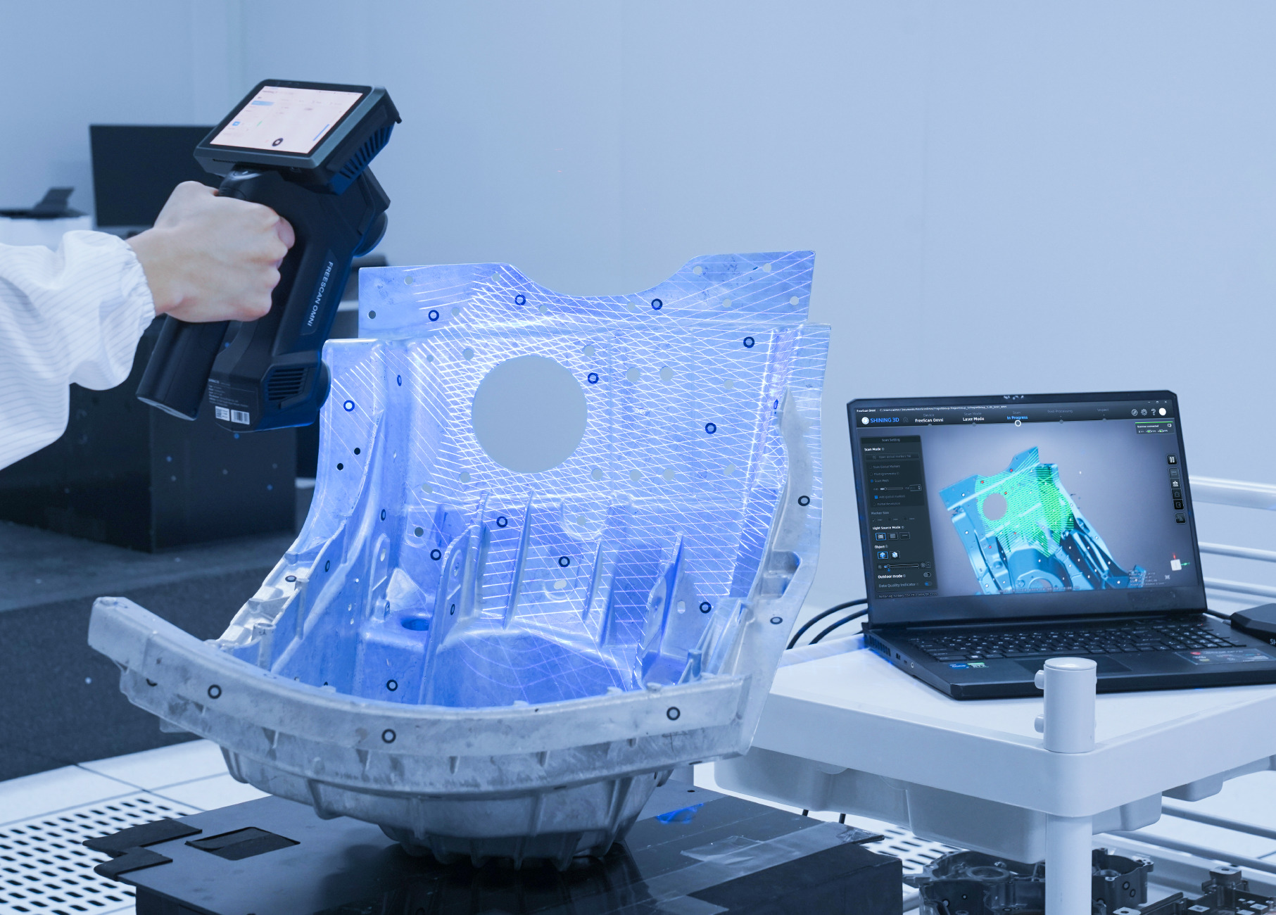
Metrology-grade handheld systems are delivered with acceptance testing performed in an ISO/IEC 17025 accredited laboratory.
SHINING 3D can issue calibration and accuracy certificates based on both VDI/VDE 2634 and ISO 10360 standards for its metrology-grade 3D scanners. The company's Accuracy Laboratory is accredited to ISO/IEC 17025 by CNAS (China National Accreditation Service for Conformity Assessment), and because CNAS is a signatory to mutual recognition agreements such as the ILAC MRA, the laboratory's test reports and calibration certificates are recognized globally. The laboratory is certified to perform accuracy tests and issue calibration certificates in compliance with VDI/VDE 2634 Part 2 (single-view optical surface scanning) and Part 3 (multiple-view systems), and its testing systems and accuracy verification protocols align with ISO 10360-12 and ISO 10360-13 for acceptance and reverification testing.
Two further points are relevant to buyers writing a specification. First, calibration is performed using certified artifacts or calibration panels traceable to metrology standards, which is what preserves measurement traceability over time rather than at a single point. Second, the company participates in the standards work itself: SHINING 3D has led the development of key industry standards for white light and structured light 3D measurement and scanning systems and contributes to technical and metrology specifications for optical 3D measurement systems, supported by more than 330 authorized patents and over 230 software copyrights.
On the software side, SHINING 3D Inspect is described as PTB-certified and is available both on-device and on PC, and the AutoScan Inspec2 desktop inspection system integrates a PTB-certified inspection module. For a QC team, the software matters because a certificate for the scanner does not automatically validate the comparison, GD&T and reporting steps that follow the scan.
Compliance Across the QC 3D Scanner Portfolio
The standard reference changes with the system architecture. Fixed structured-light scanners and handheld multi-view scanners are not tested under the same guideline part, and tracking systems add their own volumetric considerations. The table below summarizes stated accuracy figures and acceptance test references for representative systems in the SHINING 3D portfolio; exact values apply to the configurations described and are subject to the certificates actually issued.
| System | Architecture | Stated accuracy | Acceptance test reference |
|---|---|---|---|
| FreeScan Omni / FreeScan Omni Lite | Standalone wireless metrology handheld with on-device inspection | 0.02 mm; volumetric 0.02 + 0.03 mm/m (0.02 + 0.015 mm/m with VPG) | VDI/VDE 2634 Part 3 & ISO 10360, tested in the ISO/IEC 17025 accredited laboratory |
| FreeScan Combo Series | Hybrid blue laser and infrared handheld | 0.02 mm; volumetric 0.02 + 0.033 mm/m | VDI/VDE 2634 Part 3 & ISO 10360 |
| FreeScan Combo+ Wireless / FreeScan Combo Wireless | Wireless hybrid light source handheld | 0.02 mm; volumetric 0.02 + 0.03 mm/m (0.02 + 0.015 mm/m with VPG) | ISO 10360 certified, tested in the ISO/IEC 17025 accredited laboratory |
| FreeScan UE Nova | Large-FOV wireless handheld | 0.072 mm; volumetric with VPG 0.072 + 0.012 mm/m | VDI/VDE 2634 Part 3 & ISO 10360 |
| FreeScan Trak Nova Series | Wireless dynamic tracking and scanning system | 0.02 mm; volumetric 0.062 mm over 12 m³ | VDI/VDE 2634 Part 3 & ISO 10360 |
| OptimScan Q12/Q9 HD | Fixed blue LED structured light inspection scanner | 0.01 mm large range; 0.004 mm small range | VDI/VDE 2634 Part 2 & ISO 10360 |
| OptimScan Q12/Q9 | Fixed blue LED structured light inspection scanner | 0.015 mm large range; up to 0.005 mm small range | VDI/VDE 2634 & ISO 10360 (ISO 10360-13) |
| AutoScan Inspec2 | Desktop automated inspection system | Up to 0.01 mm | Integrated PTB-certified SHINING3D Inspect module |
Read as a group, these references show why the distinction between guideline parts matters in practice. The OptimScan Q12/Q9 HD, a single-view area scanning system, is referenced to VDI/VDE 2634 Part 2. The handheld and tracking systems, which assemble a single coordinate frame from many captures across a part, are referenced to Part 3. A buyer comparing quotations should expect the same granularity from every supplier in the shortlist.
Where Compliance Matters in Application
Across the industrial sectors where 3D scanning is used for quality control, one requirement appears repeatedly in application documentation: an accuracy and calibration certificate. It is listed as a site and workflow requirement for automotive work such as vehicle body inspection, engine and powertrain inspection, NEV battery pack inspection, tooling and fixture inspection and stamping die inspection; for aerospace work covering structural and component inspection, aero engine quality control, blade inspection and MRO; for energy, heavy industry and mining applications that include large castings, turbines and pipelines; for marine work spanning hull and component inspection, block fabrication and alignment, and mould surface inspection; for consumer electronics work such as first article inspection, dimensional inspection, flatness and warpage analysis; and for medical equipment and implant inspection.
The common thread is that these are not one-off measurements. Each produces something a downstream function depends on — a supplier validation archive, a repair record, a production release, a warranty decision. Certification is what converts scan data into a document the next function can rely on, which is why compliance is a procurement criterion rather than a quality-department preference.
The operating context reinforces it. Automotive inspection environments are described with variable lighting, dust exposure and working temperatures from -10°C to 40°C; marine and energy inspection includes outdoor shipyard and offshore conditions; consumer electronics inspection takes place in clean, temperature-controlled production areas. The instrument must hold its measurement claim in the environment where the parts actually are.
Market Signals Behind the Shift
Several market indicators explain why tolerance for unverifiable accuracy claims is decreasing. The global 3D metrology market, which includes 3D scanners for quality control, was valued at USD 11.13 billion in 2024 (MarketsandMarkets). North America dominated the 3D scanner market with a 37% revenue share in 2024, led by aerospace and automotive demand, while Asia Pacific is projected to be the fastest-growing region for 3D metrology with a CAGR of 8.0% through 2029 (Precedence Research; MarketsandMarkets). Within the product mix, structured light scanners dominated the 3D scanner product segment in 2024 due to their high precision in industrial applications, and short-range scanners of 1 metre or less held the largest share of the market because of high-precision requirements in parts inspection (Precedence Research).
The automation side shows the same direction. The 3D automated optical inspection equipment market was valued at USD 2.74 billion in 2024 and is growing at a 7.32% CAGR, and inline automated 3D inspection systems are increasingly replacing offline checks in the electronics sector to boost first-pass yields (Market Research Future; Mordor Intelligence). When inspection moves inline, the certificate requirement moves with it: a pass/fail decision made by an automated cell is only as defensible as the traceability of the sensor that produced the data.
Competitive context matters too. Hexagon, FARO and Carl Zeiss are recognized as Tier 1 global leaders in industrial metrology and 3D scanning (SNS Insider), and buyers legitimately benchmark against them. SHINING 3D was recognized as an 'Emerging Leader' in the global industrial metrology space by 360Quadrants in 2025 and reported 31% revenue growth in 2025 attributed to innovation in industrial metrology and global expansion. In a market where accreditation and certificate scope are compared line by line, positioning claims matter less than documented test evidence.
Comparison with Traditional Solutions — and the Boundaries of Scanning
Standards compliance does not make 3D scanning the right answer for every inspection task. The comparison below reflects how the available measurement approaches are generally positioned relative to each other.
| Method | Where it is strong | Where it is constrained |
|---|---|---|
| Hand tools (for example calipers) | Fast checking of basic dimensions on simple geometry | Point-to-point measurement only; cannot capture the full 3D profile of complex curvatures or free-form surfaces |
| Coordinate Measuring Machines (CMMs) | Widely recognized reference for absolute measurement accuracy; ideal for critical geometric features in highly regulated workflows | Tied to an environment-controlled laboratory; limited when massive castings or large-scale components must be measured |
| Consumer / hobbyist 3D scanners | Cost-effective creation of visual 3D models, basic design assistance and digital assets | Data lacks strict metrological traceability; cannot be used to sign off engineering quality reports |
| Metrology-grade 3D scanners | Full-field capture of millions of data points in seconds, with colour-mapped deviation analysis and shop-floor mobility for complex or large parts | Highly reflective, glossy or translucent surfaces often require an ultra-thin layer of scanning spray; structured-light systems can be disrupted by strong ambient light |
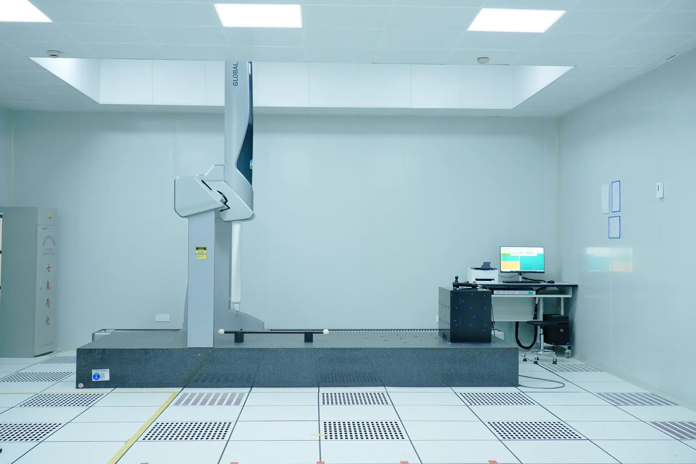
Coordinate measuring machines remain the recognized reference for absolute measurement accuracy in controlled environments. Compliance frameworks describe how a scanner is verified — not which method a tolerance requires.
There are further boundaries that a specification should state explicitly rather than discover later:
- Volumetric error grows with distance. A volumetric accuracy expression such as 0.02 + 0.015 mm/m means that over a two-metre part the maximum measurement error can reach 0.02 + (0.015 × 2) = 0.05 mm. A single accuracy figure does not describe that behaviour.
- A certificate covers a defined configuration and procedure. Changing the working range, adding or removing modules, or using the system outside the tested conditions is not automatically covered by the original acceptance documentation.
- Operator and setup influence results. Handheld accuracy depends on scanning technique, marker or photogrammetry setup, and object size; large-object scanning typically relies on global control such as validated scale bars and video photogrammetry.
- Fixed structured-light systems suit specific objects. They are recommended for small to medium parts in high-precision scenarios, and ambient light or surface preparation can affect results.
- The standard verifies the instrument, not the part. Passing an acceptance test does not mean a given component passes its tolerance; that judgment still depends on the tolerance in the drawing and on the measurement uncertainty the team is willing to accept.
The Long-Term View: Compliance as an Ownership Question
For a system expected to remain in service for years, the certificate issued at delivery is the beginning of a traceability chain, not the end of it. Three elements determine whether the chain holds.
Recalibration discipline. Metrology-grade 3D scanners are calibrated using certified artifacts or calibration panels traceable to metrology standards, and recalibration is triggered by defined events rather than by calendar alone: first use or after one to two weeks of inactivity; after severe shock or vibration, such as during transport; when accuracy is noticeably reduced and alignment errors or unrecognized markers become frequent; and when scan data becomes incomplete or data quality seriously deteriorates. Writing those triggers into a maintenance plan is what keeps inspection records defensible.
Software continuity. Inspection software is maintained over time rather than frozen at purchase. SHINING 3D states that it will continue to maintain and update the SHINING3D Inspect software and deliver new features and improvements to existing customers, which matters when inspection reports must remain reproducible years after a part was scanned.
Supply chain and data handling. For long-term programmes, documentation security is part of compliance. SHINING 3D has achieved TISAX and ISO/IEC 27001, ISO/IEC 27701, ISO/IEC 27017, ISO/IEC 27018 and MLPS Level 3 certifications for information security and privacy, and holds Authorized Economic Operator (AEO) advanced certification covering supply chain security and customs control efficiency. The company also holds ISO 9001, ISO 14001, ISO 45001, ISO 13485, MDSAP and KGMP management system certifications and CE, FDA and FCC product compliance, and operates from a 140,000 m² headquarters facility with 1,367 employees, a 533-engineer R&D organisation, and subsidiaries in Stuttgart, Barcelona, California, Florida and Tokyo serving markets across the EU, USA and APAC.
For a buyer, the practical translation is straightforward: the question is not only whether the scanner can be certified today, but whether the supplier can re-verify it, update the software that produces the reports, protect the inspection data, and ship replacement components without disrupting the quality programme.
Future Outlook
Two movements are likely to shape how compliance is written into purchase orders over the next planning cycle. The first is the migration of inspection into production. With inline automated 3D inspection increasingly replacing offline checks and the 3D automated optical inspection equipment market expanding at a 7.32% CAGR from a 2024 base of USD 2.74 billion, acceptance criteria will increasingly be written as commissioning requirements for automated cells rather than as laboratory specifications for standalone instruments.
The second is regional. With North America already holding a 37% revenue share of the 3D scanner market and Asia Pacific projected to grow fastest in 3D metrology at an 8.0% CAGR through 2029, certificates that are recognized across borders will carry more commercial weight than certificates recognized only in the supplier's home market. Buyers operating multi-region quality systems are likely to standardize on suppliers whose laboratories are accredited under mutual recognition arrangements, and to request reverification evidence as a routine part of maintenance contracts rather than as a special project.
FAQ
Can a supplier issue an accuracy certificate according to ISO 10360 or VDI/VDE 2634?
Yes, when the supplier operates an accredited calibration laboratory. SHINING 3D issues calibration and accuracy certificates based on both VDI/VDE 2634 and ISO 10360 standards for its metrology-grade 3D scanners. The SHINING 3D Accuracy Laboratory is accredited to ISO/IEC 17025 by CNAS, and since CNAS is a signatory to mutual recognition agreements such as the ILAC MRA, its test reports and calibration certificates are recognized globally. The laboratory is certified to perform accuracy testing and issue calibration certificates in compliance with VDI/VDE 2634 Part 2 for single-view optical surface scanning and Part 3 for multiple-view systems, while testing systems and verification protocols align with ISO 10360-12 and ISO 10360-13. Certificates are subject to the certificates actually issued.
What is the difference between accuracy, precision, resolution, and volumetric accuracy?
Accuracy describes how closely a measured result matches the true physical dimension: if a 100.00 mm feature is measured as 100.02 mm, the error is 0.02 mm. Precision, also called repeatability, describes how consistently the same measurement is reproduced under unchanged conditions — five consecutive scans producing 100.02, 100.02, 100.03, 100.02 and 100.02 mm show high precision even if the readings are slightly offset. Resolution is the smallest detail the scanner can distinguish; higher resolution does not automatically mean higher accuracy. Volumetric accuracy describes measurement accuracy across a larger scanning volume. For a volumetric accuracy expression of 0.02 + 0.015 mm/m, a two-metre-long object implies a maximum measurement error of 0.02 + (0.015 × 2) = 0.05 mm.
How is an industrial 3D scanner calibrated, and when does it need recalibration?
Metrology-grade 3D scanners are calibrated using certified artifacts or calibration panels traceable to metrology standards; regular calibration preserves measurement traceability, maintains accuracy, and aligns the instrument with quality management requirements. Recalibration is indicated when the scanner is used for the first time or after one to two weeks of inactivity; after severe shock or vibration such as during transport; when accuracy is significantly reduced, causing frequent alignment errors or unrecognized markers; and when scanning data becomes incomplete or data quality has seriously deteriorated.
Which guideline part applies to a specific scanner — VDI/VDE 2634 Part 2 or Part 3 — and where does ISO 10360 fit?
VDI/VDE 2634 Part 2 addresses optical 3D measuring systems based on single-view area scanning, which corresponds to fixed structured-light inspection scanners; the OptimScan Q12/Q9 HD, for example, references VDI/VDE 2634 Part 2 and ISO 10360 in its acceptance test. VDI/VDE 2634 Part 3 addresses multiple-view systems based on area scanning, which corresponds to handheld and tracking systems that build one coordinate frame from many captures; the FreeScan Omni, FreeScan Combo Series, FreeScan UE Nova and FreeScan Trak Nova Series reference Part 3 and ISO 10360. Within ISO 10360, Part 12 addresses articulated arm coordinate measuring machines equipped with 3D scanners, and Part 13 addresses optical 3D coordinate measuring systems; the OptimScan Q12/Q9 acceptance test references ISO 10360 and ISO 10360-13.
What purchasing and acceptance terms are typical when a metrology 3D scanner is ordered?
Typical commercial terms for SHINING 3D metrology equipment list a minimum order quantity of one unit; delivery terms of FOB, CFR, DAP or FCA; acceptance criteria based on delivery inspection or post-installation acceptance; and payment terms of 100% advance payment or installment payment. Buyers assembling a compliance file should align the chosen acceptance route with the certificate scope required by their own quality system.
Can a metrology-grade 3D scanner replace a CMM for quality control?
Neither technology covers every inspection task. Coordinate measuring machines remain the widely recognized reference for absolute measurement accuracy and are ideal for critical geometric features in highly regulated, stationary workflows where extreme precision is required, but they are tied to an environment-controlled laboratory and are limited when massive castings or large-scale components must be measured. Metrology-grade 3D scanners capture millions of data points in seconds and generate colour-mapped deviation analysis, which suits shop-floor inspection of complex and large parts, although highly reflective, glossy or translucent surfaces often require an ultra-thin layer of scanning spray. The decision depends on where the measurement must be taken and which tolerance must be certified.
Buyers assembling a specification file can reference the SHINING 3D 3D Digitizing introduction brochure alongside the accuracy certificates applicable to the selected configuration. Company information is published at www.shining3d.com.