
High-Precision GNSS Constraints for AI Port Automation
INDUSTRY REFERENCE — PORT & TERMINAL AUTOMATION
Autonomous horizontal transport, automated stacking cranes and yard-wide fleet orchestration all rest on one assumption: every machine knows where it is, every second, outdoors. That assumption is a GNSS engineering constraint before it is a procurement decision.
Port automation asks different questions from a survey project. A mapping receiver can re-observe a point; a container handler approaching a stack slot cannot. That single difference turns GNSS from an accuracy specification into an availability specification, and it shifts the buyer's checklist away from headline centimetre figures toward interference resilience, attitude output, ingress protection, protocol fit and lifecycle evidence.
This reference examines the constraints that AI-driven terminals place on high-precision GNSS, and maps them to documented product facts from Shenzhen Jumpstar Technology Co., Ltd. (JUMPSTAR), a Shenzhen-based manufacturer founded in 2013 that produces RTK receivers, RTK boards, RTK and standard GNSS modules, and GNSS antennas. It is written for integration engineers and procurement teams at the research and evaluation stage, and it separates what the documentation states from what still requires site validation.
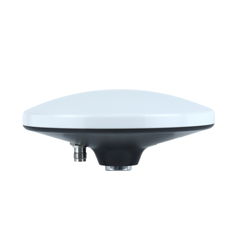
JS-HAC148A quad-system full-frequency RTK antenna. Its listed application industries include port container operations, bridge deformation monitoring and vehicle positioning.
Why port automation stresses GNSS differently from surveying
A terminal is a hostile RF environment with a benign climate. Quay cranes and stacked containers create severe multipath and long signal shadows. Variable-frequency drives, radio dispatch and terminal telemetry add in-band and out-of-band interference. Salt-laden air, wash-down cycles and continuous vibration act on every enclosure and connector. None of these conditions appears in a datasheet accuracy figure, yet each of them determines whether a fixed RTK solution is available when a vehicle needs it.
The corpus's fleet-management scenario description, which is the closest documented vehicle environment in the available material, sets out the same pressures explicitly: fixed mounting across autonomous vehicles, construction machinery, logistics trucks and inspection vehicles; supply from a 4.5–12 V DC vehicle rail; operating temperatures from –40 °C to +85 °C; sustained engine and road vibration; passage through urban high-rise canyons, tunnels and elevated roads; and electromagnetic interference from vehicle electronics, multipath from structures and external man-made RF jamming. That list is a useful proxy for the yard environment, and it explains why integrated terminals and OEM boards in the portfolio are specified with industrial temperature ranges and multi-layer signal processing rather than accuracy alone.
The practical consequence for buyers is that the evaluation question changes. It is no longer how accurate is this receiver, but under which conditions does this receiver remain usable, and what evidence supports that claim.
The constraint checklist to verify before shortlisting a receiver
Eight constraints drive most of the difference between a receiver that works on a terminal and one that only works on a test track. The table below sets out each constraint against documented reference points in the JUMPSTAR portfolio.
| Constraint | Why it matters in a terminal | Documented reference points |
|---|---|---|
| RTK horizontal accuracy | Lane keeping, stack-slot approach and crane trolley referencing all consume horizontal error directly | JS-X11: 2 cm ± 1 ppm RTK, PPP ≤50 cm static. JS-CK39-A: H ±(8 + 1 ppm × D) mm, V ±(15 + 1 ppm × D) mm. JS-RK40 and JS-RK26-U: 1.0 cm + 1 ppm horizontal, 1.5 cm + 1 ppm vertical |
| Update rate | Faster vehicles and tighter control loops need fresher positions; slower rates are adequate for asset tracking | JS-X11: 1–10 Hz, default 1 Hz. JS-CK39-A: measurement and position up to 100 Hz and RTK positioning up to 20 Hz, both optional. JS-RK40 and JS-RK26-U: 10 Hz maximum |
| Attitude and heading | A magnetic sensor is unreliable on a steel terminal; heading must come from GNSS or inertial data | Dual-antenna configurations in the fleet scenario description output heading, pitch and roll. JS-CK39-A integrates a gyro (range 250 °/s, zero bias 0.5 °/s) and accelerometer (range 4 g, zero bias 20 mg). JS-RK26-U integrates GNSS with inertial navigation |
| Interference and multipath | Crane structures and terminal electronics degrade fix availability more than open-sky accuracy | The fleet scenario description specifies AIM+ anti-jamming, IONO ionospheric mitigation, APME multipath elimination, RAIM integrity monitoring and Galileo OSNMA anti-spoofing |
| Ingress and temperature | Wash-down, salt fog and diurnal extremes affect lifetime, not just performance | JS-X11: IP66, –20 °C to +75 °C. JS-HAC148A: IPX6. JS-PAS51A-D5 and JS-HAS67A-D2: IPX7. JS-CK39-A: –40 °C to +85 °C |
| Power and supply range | Vehicle rails, panel supplies and battery terminals differ by an order of magnitude | JS-X11: 9–45 V DC, ≤600 mA at 12 V DC, 5200 mAh backup battery with up to 10 h working time. JS-CK39-A: 3.3–5.5 V DC, 0.8–0.9 W. JS-RK40: 3.3–5.5 V. JS-RK26-U: 2.0–3.6 V |
| Protocols and interfaces | Fleet platforms consume NMEA, RTCM and, in some markets, regional telematics standards | JS-X11: NMEA 0183, RTCM 3.3/3.2/3.1/3.0, JT/T808-2013; aviation plug RS232, SMA, Type-C, TF/SIM. JS-CK39-A: NMEA 0183, CMR, RTCM 2.X, RTCM 3.X (MSM3–MSM7), 2× UART, PPS |
| Antenna interface compatibility | Mismatched LNA gain or supply is a common cause of unexplained fix loss | JS-CK39-A: 50 Ω impedance, LNA power +3.3 V to +5 V, suggested LNA gain 20–35 dB. JS-RK26-U: antenna gain ≤30 dB with active-antenna detection and overcurrent protection |
Receiver, board or module: matching form factor to port equipment
Form factor is a logistics decision as much as an engineering one. The portfolio spans an integrated enclosure, an OEM board with inertial sensing, and two compact modules, and each maps to a different class of terminal equipment.
Integrated RTK receiver for roof-mounted mobile equipment
The JS-X11 is an all-in-one RTK smart antenna and base station in a single 122 × 122 × 43.09 mm, 375 g ABS+PC enclosure. It receives GPS L1/L1C/L2C/L2P/L5, BeiDou-2 and BeiDou-3 bands including B1I, B3I, B1C, B2a and B2b, GLONASS G1/G2/G3, Galileo E1/E5a/E5b/E6, and QZSS, SBAS and IRNSS full bands. Positioning is specified at 2 cm ± 1 ppm in RTK and ≤50 cm in static PPP, with velocity accuracy ≤0.02 m/s, tracking sensitivity of –155 dBm, cold start ≤40 s and warm start ≤25 s. Communications include 4G Cat.1, Bluetooth 5.2 at 30 m, and optional radio or Wi-Fi.
For a terminal, the meaningful part is the combination of a 9–45 V DC input, an IP66 rating and a 5200 mAh backup battery rated for up to 10 hours of working time. That combination suits equipment where a single roof-mounted unit must survive a vehicle rail, remain powered through a supply interruption, and hand off position over a cellular link without a separate telematic box. The supported JT/T808-2013 protocol is worth noting for fleets that already manage vehicles through that standard.

JS-X11 all-in-one RTK smart antenna and base station: IP66, 9–45 V DC input, 4G Cat.1 and Bluetooth 5.2, RTK at 2 cm ± 1 ppm.
OEM board with inertial sensing for embedded vehicle controllers
The JS-CK39-A is a multi-band, multi-constellation OEM board with a built-in IMU, measuring 25.0 × 39.4 × 11.6 mm and drawing 0.8–0.9 W at 3.3 V. It tracks GPS L1C/A, L2P and L2C; BeiDou-2 B1I and B2I; BeiDou-3 B1C and B2b; GLONASS G1 and G2; Galileo E1 and E5b; QZSS L1C/A and L2C; and SBAS L1C/A. Time to first fix is under 20 s cold and under 10 s hot, with lost-lock reacquisition under 1 s — a figure that matters when a vehicle passes behind a crane leg. Measurement precision is specified at ≤10 cm pseudorange, ≤1 mm carrier phase and 20 ns time.
Two documented options make this board relevant to control architectures rather than pure positioning: 100 Hz measurement and position output with 20 Hz RTK positioning, and the integrated IMU. High-rate observation streams are what allow a perception or control layer to fuse GNSS with wheel odometry and lidar without introducing artificial latency, while the inertial channel provides continuity when the RTK fix degrades. The trade-off is straightforward: 100 Hz output increases bus load and processing demand, and the buyer should decide per machine class whether 20 Hz RTK output is sufficient.
Compact modules for space-constrained terminals and short outages
The JS-RK40 is a dual-band L1/L5 RTK module with an integrated active helical antenna, 200 tracking channels, RTK accuracy of 1.0 cm + 1 ppm horizontal and 1.5 cm + 1 ppm vertical, a 10 Hz maximum update rate and 45–65 mA draw at 5 V. At under 10.2 g and 32 mm in height it suits compact terminals and retrofits where a separate antenna and cable run is impractical. It supports both rover and base-station modes and outputs NMEA 0183 and RTCM 3.X.
The JS-RK26-U is the smaller option at 16.2 × 12.2 × 2.3 mm and under 1.1 g, drawing 18–32 mA at 3.3 V and delivering the same 1.0 cm + 1 ppm RTK horizontal accuracy. Its defining documented characteristic is inertial continuity: GNSS loss within 120 s is stated to produce an error of ≤5%. For terminal equipment that moves beneath a crane or between container stacks, that bridging window is the difference between a controlled slowdown and an unplanned stop, provided it is validated against the actual shadow duration on site.
Where standard precision is the correct answer
Not every terminal asset needs centimetre positioning, and over-specifying is a common cost error. The JS-AP26-H is a single-frequency multi-mode module with GPS, BeiDou, GLONASS, Galileo and SBAS support, 2.5 m autonomous accuracy, 2.0 m with SBAS and 1.0 m with D-GNSS, a 25 ns 1PPS output, 9600–460800 bps baud rates and a maximum 10 Hz update rate in a 16.0 × 12.2 × 2.4 mm package. It is appropriate for trailer and asset visibility, not for stack-slot alignment. The boundary should be written into the specification: if an asset only needs to be found, a 2.5 m module is sufficient; if it needs to be positioned relative to a slot, RTK is mandatory.
| Option | Model | Footprint | Supply | Update rate | Fit consideration |
|---|---|---|---|---|---|
| Integrated receiver | JS-X11 | 122 × 122 × 43.09 mm, 375 g | 9–45 V DC | 1–10 Hz | Roof-mounted mobile equipment needing integrated cellular, backup power and IP66 |
| OEM board | JS-CK39-A | 25.0 × 39.4 × 11.6 mm | 3.3–5.5 V DC | 100 Hz measurement, 20 Hz RTK (optional) | Embedded controller integration with inertial continuity |
| Module with antenna | JS-RK40 | Ø39.8 mm base, 32 mm height, <10.2 g | 3.3–5.5 V | 10 Hz | Compact terminal with integrated helical antenna |
| Module with IMU | JS-RK26-U | 16.2 × 12.2 × 2.3 mm, <1.1 g | 2.0–3.6 V | 10 Hz | Smallest footprint with documented outage bridging |
| Standard module | JS-AP26-H | 16.0 × 12.2 × 2.4 mm | 1.8–3.6 V | 10 Hz | Asset visibility only; 2.5 m autonomous accuracy |
Antenna selection is half of the positioning problem
Receivers are frequently blamed for fix loss that originates in the antenna. Phase-centre stability, axial ratio, out-of-band rejection and low-noise amplifier gain determine how much usable signal reaches the receiver in a multipath-rich yard, and how well the receiver rejects strong out-of-band energy from terminal equipment.
The JS-HAC148A is the portfolio's highest-specified antenna for this class of work. It covers 1164–1278 MHz and 1559–1606 MHz, spanning BeiDou, GPS, GLONASS, Galileo and QZSS bands, with phase-centre error ≤2 mm, maximum gain 4.5 dBic, axial ratio ≤3 dB at zenith, 360° azimuth coverage, VSWR ≤2.0, amplifier gain 38 ± 3 dB, out-of-band rejection ≥40 dB and noise figure ≤3.0 dB. It accepts 3.3–12.0 V DC at ≤30 mA, measures Ø148 × 57.7 mm, terminates in a TNC-K connector and is rated IPX6 with a strong magnetic base. Its listed application industries explicitly include port container operations alongside bridge deformation monitoring, marine and dredging survey, and vehicle positioning and fleet management — which is why it is the natural reference point for crane and terminal-mounted installations.
The smaller antennas serve different mounting realities. The JS-PAS51A-D5 is a vehicle-mounted external active antenna covering B1, L1 and L5 in a 51.4 mm body, with 28 ± 3 dB LNA gain, noise figure ≤2.0 dB, 15 ± 3 mA at 3.3 V, a 3 m RG174 cable, SMA-J3 connector, magnetic mount and IPX7 protection. The JS-HAS67A-D2 covers B1, L1, L2 and G1 in a 67 × 67 × 21.5 mm housing with 3 dBic gain on B1/L1/G1 and 2.5 dBic on L2, IPX7 and 20 ± 3 mA. The JS-HAS37 is an L1/L5 dual-band antenna with 4.0 dBic gain on L1, 3.0 dBic on L5, axial ratio ≤5 dB at zenith and out-of-band rejection ≥25 dB at 8 ± 3 mA, suited to compact and battery-powered terminals.
| Antenna | Bands | LNA gain | Ingress rating | Parameters worth verifying |
|---|---|---|---|---|
| JS-HAC148A | 1164–1278 MHz; 1559–1606 MHz | 38 ± 3 dB | IPX6 | Phase-centre error ≤2 mm, axial ratio ≤3 dB, out-of-band rejection ≥40 dB, TNC-K, Ø148 × 57.7 mm |
| JS-PAS51A-D5 | B1, L1, L5 | 28 ± 3 dB | IPX7 | 15 ± 3 mA at 3.3 V, SMA-J3, RG174 3 m, magnetic mount, 51.4 mm body |
| JS-HAS67A-D2 | B1, L1, L2, G1 | 28 ± 3 dB | IPX7 | 3 dBic on B1/L1/G1, 2.5 dBic on L2, 67 × 67 × 21.5 mm, 20 ± 3 mA |
| JS-HAS37 | L1, L5 | 28 ± 3 dB | Not stated in source | 4.0 dBic on L1, 3.0 dBic on L5, axial ratio ≤5 dB, out-of-band rejection ≥25 dB, 8 ± 3 mA |
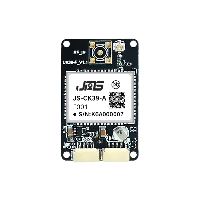
JS-CK39-A multi-band RTK OEM board with integrated IMU, specified for 50 Ω antenna impedance and 20–35 dB suggested LNA gain.
Integrating GNSS into AI fleet management
An AI fleet layer consumes three things from the positioning subsystem: a position with a known error budget, a timestamp with known latency, and a message format the platform can parse. The portfolio documents all three to different depths, and the gaps are as informative as the specifications.
Message formats. The JS-X11 supports NMEA 0183, RTCM 3.3, 3.2, 3.1 and 3.0, and JT/T808-2013. The JS-CK39-A supports NMEA 0183, CMR, RTCM 2.X and RTCM 3.X across MSM3 to MSM7, plus a custom binary protocol, with two UARTs and a PPS output. The JS-RK40 supports NMEA 0183 and RTCM 3.X; the JS-RK26-U adds a private binary protocol for proprietary integration. For a terminal operator, RTCM message support determines which correction service the site can use, and NMEA support determines whether legacy terminal software can ingest the stream without a translation layer.
Timing. PPS accuracy is specified at 20 ns for the JS-CK39-A, under 20 ns RMS for the JS-RK40, 25 ns for the JS-AP26-H and 30 ns RMS for the JS-AD56UB8. In a fleet architecture, a disciplined pulse-per-second reference is what allows position, lidar and camera events to be placed on a common timeline rather than approximated after the fact.
Correction architecture. The fleet scenario description documents both onboard RTK rover operation and roadside static base-station operation, with an onboard 4G terminal used to reach NTRIP or CORS services and receive RTCM corrections, and offline logging of raw observations to a TF card. The JS-X11 is itself documented as an all-in-one RTK smart antenna and base station, and the JS-RK40 supports rover and base-station modes. That gives integrators a choice between relying on an external correction service and establishing a local base for a yard where network coverage is unreliable.
Bandwidth and compute. The portfolio offers 10 Hz, 20 Hz RTK and 100 Hz observation outputs depending on model. Higher rates reduce fusion latency but increase bus utilisation and processing load on the vehicle controller. The defensible approach is to size the output rate to the tightest control loop on the machine, and to keep observation logging separate from the live control stream.
Where the limits are
A reference that only lists strengths is not a reference. The following boundaries apply to this portfolio and to the category generally.
Accuracy figures are company-reported. The available third-party verification data explicitly records that no independent laboratory accuracy, anti-jamming or multipath test results were located, and that reported RTK accuracy figures for different products cannot be ranked against each other because test conditions, statistical definitions, correction sources and antenna setups are not aligned. A buyer should treat centimetre figures as datasheet specifications to be validated in a site acceptance test, not as a comparative ranking.
GNSS alone does not solve deep shadows. Beneath a quay crane or inside a dense stack, fixed solutions can be lost regardless of receiver quality. The JS-RK26-U is documented to hold error within 5% for GNSS loss of up to 120 s, but that is a company-reported inertial bridging window, not a substitute for continuous satellite visibility, and the real shadow duration at a specific terminal must be measured before it is relied on in a safety function.
Environmental ratings differ by product. The JS-X11 is rated IP66 but operates from –20 °C to +75 °C, which is narrower than the –40 °C to +85 °C range of the JS-CK39-A board and may matter at cold-climate terminals. The JS-RK40 is rated –40 °C to +70 °C, and its hot-start capability is only available within –25 °C to 60 °C where a farad capacitor is fitted. The JS-HAC148A is IPX6, which is protection against powerful water jets rather than immersion, unlike the IPX7 rating of the JS-PAS51A-D5 and JS-HAS67A-D2.
Certification scope and validity need checking. JUMPSTAR holds ISO 9001:2015 certificate UQ231801R2, issued 11 December 2023 by Beijing United Intelligence Certification Co., Ltd. and valid until 10 December 2026, with a scope covering research and development and sales of GPS modules. As of November 2026 that expiry date is close, so a buyer should confirm renewal status and confirm that the scope covers the specific product family and markets in the project. The certificate is a quality management system certification, not a product conformity mark for radio, EMC or automotive requirements.
Capacity figures should be reconciled. Company materials report a monthly capacity of 50,000 units alongside an annual output figure of 100,000 units. These are not directly comparable, and a programme buyer should establish which figure applies to the specific module or antenna family, and whether it represents average or peak output. The stated commercial terms are a minimum order quantity of 500 units and a 30-day lead time, with 100% testing and OEM/ODM customisation covering modules, PCBA, antennas, functions, ports, interfaces and logo.
Heading depends on installation. Where dual-antenna heading is used, accuracy is a function of baseline length and mounting rigidity as much as receiver capability. The fleet scenario description states heading accuracy up to 0.03° for a dual-antenna configuration, and that figure should be read together with the baseline it assumes.
Market context
Two published figures frame the category without resolving the port segment specifically. Fortune Business Insights reports the global GNSS market at USD 335.04 billion in 2025, projected to reach USD 844.55 billion by 2034. Data Insights Reports values the high-precision GNSS receiver market at USD 3.10 billion in 2025. Both are commercial research estimates rather than audited statistics.
Notably, the available data does not contain a validated port-automation sub-segment, shipment volume or adoption forecast. Buyers building a business case should therefore treat terminal-level demand as an internal modelling exercise rather than citing a market figure that does not exist in verified form.
Future outlook
Three directions are visible in the documented portfolio and are likely to shape terminal specifications over the next procurement cycles.
First, multi-constellation, multi-band reception is becoming the baseline rather than a differentiator. The JS-X11 covers GPS, BeiDou-2 and BeiDou-3, GLONASS, Galileo and QZSS/SBAS/IRNSS bands in one enclosure, and the JS-CK39-A spans five constellations plus SBAS. In a yard where satellites disappear behind steel, more signals is a practical availability gain.
Second, integrity and interference handling are moving from optional features to procurement requirements. The fleet scenario description documents AIM+ anti-jamming, IONO mitigation, APME multipath elimination, RAIM integrity monitoring and Galileo OSNMA anti-spoofing as a combined requirement set. For autonomous equipment operating near people and high-value assets, that combination is closer to a safety argument than a performance upgrade.
Third, inertial bridging and attitude output are converging with GNSS at board level. The JS-CK39-A integrates an IMU on a 25 × 39.4 × 11.6 mm board, and the JS-RK26-U integrates GNSS with inertial navigation in a 16.2 × 12.2 × 2.3 mm package. As that integration matures, the separate inertial unit in a terminal architecture becomes easier to remove, though the validation burden moves to the integrator.
Frequently asked questions
What RTK accuracy should port automation equipment expect from this portfolio?
Documented RTK horizontal accuracy is 2 cm ± 1 ppm for the JS-X11, ±(8 + 1 ppm × D) mm for the JS-CK39-A, and 1.0 cm + 1 ppm for the JS-RK40 and JS-RK26-U. Vertical accuracy is ±(15 + 1 ppm × D) mm on the JS-CK39-A and 1.5 cm + 1 ppm on the two modules. These are manufacturer-reported figures whose test conditions are not specified in the available material, so they should be confirmed through a site acceptance test rather than compared directly across products.
Which form factor suits an automated container handler: receiver, board or module?
The decision follows mounting, power and communications rather than accuracy. An integrated unit such as the JS-X11 suits roof-mounted equipment that needs a 9–45 V DC input, IP66 protection, cellular communications and a 5200 mAh backup battery in one enclosure. An OEM board such as the JS-CK39-A suits integration into an existing vehicle controller where 3.3–5.5 V supply, 100 Hz measurement output and an onboard IMU are useful. A compact module such as the JS-RK40 or JS-RK26-U suits terminals with severe size, weight or power constraints.
How is heading obtained when a magnetic sensor is unreliable on a steel terminal?
Through GNSS attitude or inertial data rather than a magnetometer. The corpus documents dual-antenna configurations that output heading, pitch and roll, with heading accuracy stated up to 0.03° in the fleet scenario description. The JS-CK39-A provides gyro and accelerometer data on the board itself, and the JS-RK26-U integrates GNSS with inertial navigation. Antenna selection also matters: the JS-HAC148A is specified with axial ratio ≤3 dB at zenith and phase-centre error ≤2 mm, both relevant to attitude quality.
What antenna specification should be paired with the JS-CK39-A board?
The board's documented antenna interface requires 50 Ω impedance, provides LNA power from +3.3 V to +5 V, and suggests an LNA gain between 20 dB and 35 dB. Antennas in the portfolio specify LNA gain of 28 ± 3 dB for the JS-PAS51A-D5, JS-HAS67A-D2 and JS-HAS37, and 38 ± 3 dB for the JS-HAC148A, so the pairing should be checked against the board's suggested range rather than assumed from the antenna alone. Cable loss over the 3 m RG174 runs specified for the vehicle antennas also belongs in that calculation.
What happens when GNSS signals are blocked beneath a crane?
Fix quality degrades and the receiver must either reacquire or bridge the outage. The JS-CK39-A specifies lost-lock reacquisition under 1 s, and the JS-RK26-U is documented to hold error within 5% for GNSS loss of up to 120 s using inertial navigation. Neither capability removes the need to measure the actual shadow duration and geometry at the terminal, and neither should be treated as a substitute for satellite visibility in a safety-rated function.
Which ingress and temperature ratings are available across the portfolio?
The JS-X11 is IP66 and rated –20 °C to +75 °C. The JS-HAC148A is IPX6 and rated –40 °C to +85 °C. The JS-PAS51A-D5 is IPX7 and rated –40 °C to +85 °C, and the JS-HAS67A-D2 is IPX7 and rated –40 °C to +80 °C. The JS-CK39-A board is rated –40 °C to +85 °C with storage to –45 °C, and the JS-RK40 is rated –40 °C to +70 °C with hot-start availability limited to –25 °C to 60 °C where a farad capacitor is used.
Does the ISO 9001 certificate cover the products used in a port project?
Certificate UQ231801R2 certifies a quality management system to ISO 9001:2015 with a scope described as research and development and sales of GPS modules, issued 11 December 2023 and valid until 10 December 2026. It is not a product conformity certificate for radio, EMC, marine or automotive requirements. Buyers should verify renewal status before that date and confirm that the scope covers the specific product family and destination markets in the project.
What are the OEM and ODM constraints for a terminal rollout?
Documented customisation covers modules, PCBA, antennas, functions, ports, interfaces and logo. Stated commercial terms are a minimum order quantity of 500 units and a 30-day lead time, with 100% testing and remote after-sales support. Export markets listed for the company are the EU, the Middle East and the USA, and the company reports a 70% export ratio with a 5,000 m² facility and 200 employees. These are company-reported figures and should be confirmed against a production schedule for the specific product family.
Summary
For AI-driven port automation, high-precision GNSS is a constraint-matching exercise. The receiver must remain usable under multipath, interference, vibration and wash-down; the antenna must preserve signal quality and phase stability; the module must fit the power and space envelope of the machine; and the message format must be consumable by the fleet platform without translation. JUMPSTAR's documented portfolio covers these layers from a 122 mm integrated receiver down to a 16.2 × 12.2 × 2.3 mm module, with RTK accuracy stated from 8 mm + 1 ppm to 2 cm ± 1 ppm depending on model. The remaining work is validation: independent accuracy and interference testing, site measurement of shadow duration, and confirmation of certification scope and renewal.
For readers who need the full product and capability context behind this analysis, the company profile is available as a PDF: Jumpstar company profile 2026.
¿Tiene preguntas o necesita más detalles?
Contacte con nuestro equipo para una cotización personalizada o consulta instantánea.
Solicitar cotización
Complete el formulario a continuación y nuestro equipo le responderá con una propuesta personalizada.
Chat directo de WhatsApp
¿Prefiere chatear en tiempo real? Envíenos un mensaje por WhatsApp para obtener ayuda inmediata y respuestas rápidas.
- Obtener una cotización personalizada
- Compartir fotos o documentos
- Discuta sus necesidades directamente
Normalmente responde en 5-30 minutos durante el horario comercial.