
Hall Effect vs Current Transformer: DC and AC Buyer Guide
Hall Effect vs Current Transformer: DC and AC Buyer Guide
The choice between a Hall-effect current transducer and a transformer-based current sensor is settled by the current at the measurement point, not by the supplier list. A steady or unipolar direct current will not transfer through a magnetic core the way an alternating current does, and that single physical difference separates DC monitoring in PV strings, variable-frequency-drive (VFD) DC bus links and EV charging leakage detection from AC monitoring on feeders, meters and switchgear.
This buyer comparison maps the boundary between the two families rather than declaring a winner. It uses HEYI Electrical’s DC-side devices — the C2/C3 split-core Hall-effect current transducer and DC current transmitter, and the HYCA 6 mA DC leakage current sensor/RDC-PD — alongside its AC-side options, the KCT-L True RMS transmitter and the FRC flexible Rogowski coil (245 mm inner diameter, 100–10000 A, non-saturating). HEYI Electrical (Wenzhou Heyi Electrical Co., Ltd.) is a Chinese manufacturer of current transformers and current sensors established in 2012, whose product range is published at heyiele.com. Neither family is ranked here: each has a fit boundary, and the closing matrix turns that boundary into procurement questions.
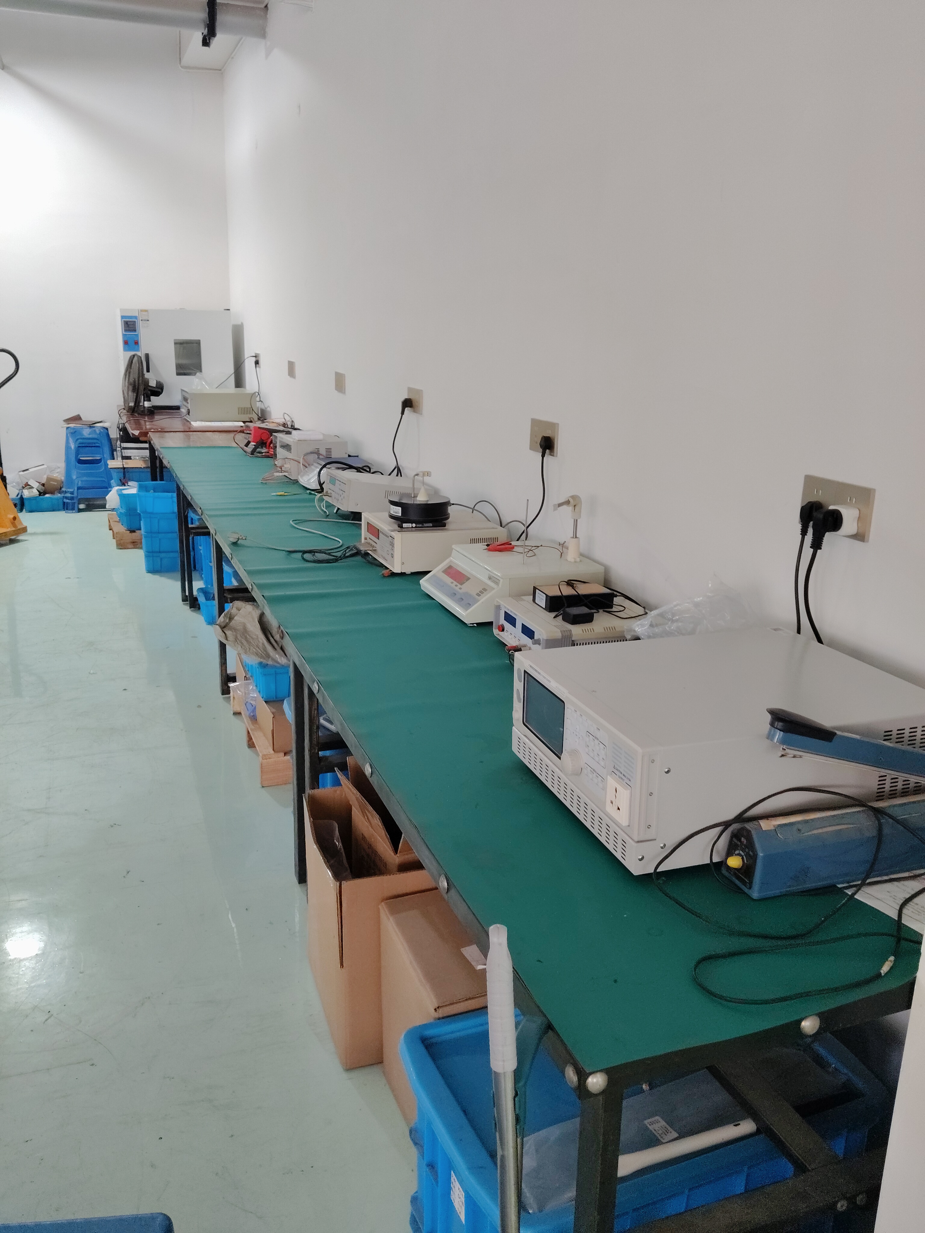
Instrument-transformer production environment: the AC side of the comparison is a wound, calibrated component, not a generic sensor.
Why the current decides the sensor family
An inductive current transformer works by magnetic coupling. Primary current produces flux in a core, and the secondary winding delivers a scaled current to a meter, relay or transducer. The coupling depends on a changing flux, which is why a conventional AC current transformer tracks an alternating waveform and not a steady one.
A Rogowski coil current transformer takes a different construction route. The winding sits on an air core rather than a magnetic core, so the output follows the rate of change of current and needs an integrator to reconstruct the measured value. Because there is no iron core to drive into saturation, the coil can reasonably be described as non-saturating, and it can be built in large flexible diameters: HEYI’s FRC coil is listed at 245 mm inner diameter for a 100–10000 A range.
Hall-effect sensing converts the magnetic field around the conductor into a voltage inside a semiconductor element. It responds to DC as well as AC and does not depend on a changing flux, which is the property that makes Hall-effect transducers and transmitters the practical option where current can sit at a high value without changing.
Where transformer-based sensing stops
A transformer cannot deliver a steady secondary output from a steady primary current. In PV string monitoring and VFD DC bus measurement, the quantity of interest frequently includes that steady component, so an AC current transformer placed on the conductor will not answer the question being asked. IEC 61869-14:2018, which addresses current transformers for DC applications above 1.5 kV, exists because DC measurement is a separate requirement rather than a variation of the AC case.
Saturation is the second boundary. An iron-cored CT rated for a defined burden can be driven into saturation by fault current or by a DC component riding on an AC waveform, and once the core saturates the secondary no longer reproduces the primary. Air-core Rogowski coils avoid that mechanism, and Hall-effect devices do not rely on core coupling at all. The trade-off is not free: a coil’s derivative output moves the accuracy burden into the integrator electronics, and a Hall transducer carries its own zero-point and temperature behaviour to manage.
Frequency is the third boundary. IEC 61869-2:2012 applies to newly manufactured inductive current transformers used with measuring instruments and protective devices at rated frequencies from 15 Hz to 100 Hz. Where the waveform is rich in harmonics — increasingly common in inverter-dominated plants — the buyer has to check the declared frequency response instead of assuming the 50 Hz case covers the installation. Mordor Intelligence’s market reporting attributes Rogowski coil adoption to harmonic monitoring and to flexibility in tight spaces; that is a third-party observation about the technology, not a certification of any specific model.
Where Hall-effect sensing starts — and what to verify
Hall-effect transducers and transmitters cover the cases the transformer cannot: battery and DC bus current, PV string current with a unipolar component, and low-level DC leakage. The devices are galvanically isolated and normally deliver a conditioned low-level analogue signal, which suits PLCs, data loggers and inverter controllers directly, without the burden calculation an AC secondary requires.
Four checks decide whether a given Hall-effect unit is suitable:
- Zero-point and offset drift over temperature. A DC measurement has no zero crossing to re-reference against, so offset behaviour sets the usable resolution at low current.
- Linearity at both ends of the range. Performance near rated current and at a small fraction of it are separate questions.
- Transducer or bare sensor. Some devices include signal conditioning and a defined output; others require external electronics. The receiving equipment decides which is acceptable.
- Behaviour under overload and the supply arrangement. Loop-powered, auxiliary-supplied and self-powered units are not interchangeable at the panel design stage.
None of that makes Hall-effect devices the better AC instrument. Where a revenue-grade reading is required, a revenue grade current transformer with a declared accuracy class remains the reference instrument, and HEYI’s core CT range is stated at accuracy classes up to 0.5/0.2 depending on model. The defensible formulation is that each family answers a different question, and the model specification — not the family name — determines whether the answer is good enough.
How the HEYI range splits along that boundary
On the DC side, HEYI positions the C2/C3 split-core Hall-effect current transducer and the DC current transmitter for PV string monitoring and VFD DC bus measurement. The split-core format matters as much as the sensing principle: a clamp-on Hall transducer can be placed on a string conductor or a DC busbar without dismantling the connection, which is the difference between a monitoring upgrade and a shutdown.
For residual direct current, HEYI lists the HYCA 6 mA DC leakage current sensor/RDC-PD. The company describes the HYCA series as a Type B residual-current sensor for charging-pile applications and states compliance with IEC 62955, IEC 62752 and UL 2231. Those are manufacturer statements, and they should be treated as such: certificate numbers, issuing bodies, validity dates and the exact model scope need to be checked before the part is designed into a charger, because a product page does not by itself establish conformity or market access.
On the AC side the range returns to transformer-based sensing. The KCT-L True RMS transmitter addresses AC circuits where the waveform is not a clean sinusoid and a true-RMS value is wanted — a measurement approach that reports the effective value of a distorted waveform rather than an average-based approximation. The FRC flexible Rogowski coil covers clamp-on AC measurement on large conductors and busbars, with the 245 mm inner diameter, 100–10000 A range and non-saturating air-core behaviour described above.
The conventional core CT line remains the metering and switchgear instrument: accuracy classes up to 0.5/0.2 depending on model, with customizable ratios such as 100/5A, 500/5A, 1000/5A and 2000/5A, applied in low-voltage switchgear, power distribution cabinets, energy metering systems, commercial buildings and industrial control panels. Split-core versions reduce installation time by 50%–70% in retrofit projects compared with traditional closed-core CTs, according to HEYI’s product documentation. For supplier screening context, HEYI reports a 10,000 m² factory, an annual output of 356,000 units and a 95% export share — company-reported figures that support an initial shortlist, not an independent audit.
Application fit: four monitoring points
PV string monitoring
String current is unipolar and includes a steady component, so the measurement belongs on the DC-capable side of the boundary. A split-core Hall-effect transducer allows per-string instrumentation without opening the string, and the specification question shifts to offset stability at low irradiance, supply arrangement and connector compatibility with the monitoring unit.
VFD DC bus measurement
The DC link carries a direct current with ripple, so the transducer has to be adequate for both the steady value and the ripple content. Here the buyer should ask for the declared bandwidth and the isolation rating rather than rely on a generic “DC sensor” description; an AC current transformer on the same busbar answers a question nobody asked.
EV charging and DC leakage
Residual DC detection is a safety function, not a metering function, and it is the point where documentation matters more than the datasheet headline. A 6 mA DC leakage current sensor such as the HYCA/RDC-PD should be selected against the charger’s own protection architecture, with the claimed standard conformity supported by the certificate and the test report for the exact model.
AC feeders, meters and switchgear
Balanced or distorted AC feeders remain the territory of the current transformer and, where the conductor is large or the shutdown is unacceptable, the Rogowski coil. A three phase current transformer set with a declared accuracy class serves billing and load monitoring; a true-RMS transmitter or a flexible coil serves retrofit monitoring on existing busbar. In both cases the output must match the receiving meter, relay or PLC input.
Clamp-on installation and the real cost of a shutdown
Installation architecture often decides the purchase as much as accuracy does. A closed-core CT requires the conductor to be disconnected; a split-core current transformer or a clamp current transformer opens and closes around an existing cable, which matters in retrofits of switchgear, busbar chambers and operating PV arrays. The same logic applies on the DC side, where a split-core Hall-effect transducer is mounted without breaking the string.
Clamp-on designs do not remove engineering checks. Core mating faces must be clean and fully closed, polarity and wiring labels matter more than in a factory-wired panel, and the secondary or signal cable has to match the receiving device. HEYI’s stated production controls include polarity test, ratio test, insulation resistance and withstand voltage testing, accuracy calibration and 100% routine inspection before shipment — controls aimed at exactly the failure modes that field installation makes easy to introduce.
Standards and evidence to request before an order
Three IEC documents define the requirement scopes a buyer will meet in this category, and none of them is a certificate. IEC 61869-2:2012 covers inductive current transformers at rated frequencies of 15 Hz to 100 Hz; IEC 61869-10:2017 covers low-power passive current transformers with analogue output; IEC 61869-14:2018 covers current transformers for DC applications above 1.5 kV. A supplier claim of conformity has to be tied to a model and a document.
- Model-level datasheet stating ratio, accuracy class, burden or output, supply, temperature range and window or aperture dimensions.
- Type test reports supporting the declared accuracy class, not a generic catalogue statement.
- Routine test records for the delivered batch, including ratio and insulation tests.
- Certificate scope for any IEC 62955, IEC 62752 or UL 2231 claim — number, body, validity and the exact models covered.
- Application evidence on the buyer’s own receiver: a sample measured through the actual meter, relay or PLC input, at the actual current range.
Market context: why the DC side draws more attention
Published commercial research places the global current transformer market at USD 3.06 billion in 2026, rising to USD 5.23 billion by 2034 at a reported 6.92% CAGR (Fortune Business Insights, publisher estimate). The figure is directional only: the market boundary and methodology were not validated in our review, so it should not carry a sourcing decision by itself. More useful for a buyer is the structural observation that standards now separate inductive AC, low-power passive and DC-application current transformers, while DC measurement points have multiplied with PV, storage and DC-linked drive systems. That is a description of the requirement landscape, not a forecast of any individual project.
Side-by-side buyer matrix
| Decision criterion | Hall-effect transducer / transmitter | Inductive current transformer | Rogowski coil |
|---|---|---|---|
| DC or unipolar current | Yes — responds to a steady field; used for PV strings, VFD DC bus, DC leakage | No steady secondary output; DC application is a separate standard scope (IEC 61869-14) | Not for steady DC; derivative output of an unchanging current is zero |
| AC measurement | Capable, but offset and drift behaviour must be checked per model | Core competence; accuracy classes up to 0.5/0.2 depending on model | Capable with an integrator; suited to large conductors |
| Distorted waveform / harmonics | Check declared bandwidth | Check declared frequency response; IEC 61869-2 scope is 15–100 Hz | Wide-band air-core design, cited by third-party research for harmonic monitoring |
| Saturation behaviour | No magnetic core coupling to saturate | Can saturate under fault current or a DC component on the AC waveform | Non-saturating air core (FRC: 245 mm ID, 100–10000 A) |
| Clamp-on installation | Split-core C2/C3 transducer mounts without breaking the conductor | Split-core versions reduce retrofit installation time by 50%–70% versus closed-core | Flexible coil for busbar and tight spaces |
| Output type | Conditioned low-level analogue signal for PLC, logger or controller | AC secondary current or low-level output; burden applies | Voltage proportional to di/dt; requires an integrator |
| Verify before ordering | Offset drift, linearity at low current, supply, overload behaviour | Accuracy class, burden, type test report, ratio | Coil diameter, integrator accuracy, phase behaviour, cable routing |
Matrix summarises documented characteristics of each sensing approach; model-level specifications must be confirmed on the individual datasheet.
A five-step decision sequence
- Classify the current. Is there a steady or unipolar component, or is it a periodic AC waveform? This single answer removes roughly half the catalogue.
- Classify the waveform quality. Clean sinusoid, distorted AC, or DC with ripple. It determines whether an accuracy class, a true-RMS measurement or a declared bandwidth is the governing specification.
- Check whether the conductor can be disconnected. If not, the shortlist narrows to split-core and clamp-on formats, on either side of the family boundary.
- Start from the receiver, not the sensor. A 5 A or 1 A secondary, a low-level analogue signal and a derivative output requiring integration are not interchangeable at the panel.
- Fix the evidence package before price comparison. Datasheet, type test, routine test and certificate scope for the exact model — then compare quotations on equal documentation.
Applied in that order, the Hall-effect versus current-transformer question usually resolves itself before the negotiation stage: DC and leakage points go to Hall-effect transducers and residual-current sensors, metering and switchgear go to core current transformers, and large-conductor or harmonic-rich AC retrofits go to a Rogowski coil. HEYI covers all three positions in its published portfolio, which makes it a useful single source for a mixed project — provided each model is qualified on its own documents rather than on the breadth of the range.
Buyers who want the underlying product and capability data can review the company brochure for the current transformer and sensor range: HEYI Electrical product brochure (PDF). Technical questions on model selection can be directed to the manufacturer at bethy@heyiele.com.
FAQ
Can a standard current transformer measure DC current?
No, not in the steady-state sense. An inductive current transformer depends on a changing magnetic flux to induce a secondary current, so a constant direct current produces no sustained secondary output. IEC 61869-2:2012 scopes inductive current transformers to rated frequencies of 15 Hz to 100 Hz, while DC measurement falls under a separate document, IEC 61869-14:2018, for DC applications above 1.5 kV. DC current is therefore measured with Hall-effect transducers, DC current transmitters or dedicated DC-capable devices.
Why is a Rogowski coil described as non-saturating?
A Rogowski coil has no magnetic core — the winding sits on an air core — so there is no iron to drive into saturation under fault current or a DC offset on the AC waveform. Its output is proportional to the rate of change of current and must be integrated to reconstruct the measured value, which places the accuracy burden on the integrator electronics. HEYI’s FRC flexible coil is listed at 245 mm inner diameter for a 100–10000 A range.
Do split-core sensors require the cable to be disconnected during installation?
A split-core or clamp-on sensor opens and closes around an existing conductor, so the cable does not have to be disconnected. HEYI states that split-core current transformer models reduce installation time by 50%–70% in retrofit projects compared with traditional closed-core CTs. Installation still requires clean, fully closed core mating faces, correct polarity and wiring consistent with the receiving meter, relay or PLC input.
How does output type change the choice between these sensing methods?
Inductive current transformers deliver an AC secondary current, typically 5 A or 1 A, or a low-level output, and the connected device must accept that burden and signal form. Hall-effect transducers and transmitters normally provide a conditioned low-level analogue signal suited to PLCs, loggers and controllers. Rogowski coils output a voltage proportional to di/dt and need an integrator. Because these forms are not interchangeable at the panel, the receiving equipment should be specified before the sensor is ordered.
Is a Hall-effect sensor less accurate than a current transformer?
There is no general ranking, because the two answer different measurement questions. Metring-grade AC work is referenced to a current transformer with a declared accuracy class — HEYI’s core CT range is stated at up to 0.5/0.2 depending on model — while Hall-effect devices carry offset and temperature drift that must be evaluated against the required resolution at low current. The decision criterion is the function being measured: billing and protection on AC circuits, or steady DC and residual-current monitoring where a transformer cannot produce a usable signal.
¿Tiene preguntas o necesita más detalles?
Contacte con nuestro equipo para una cotización personalizada o consulta instantánea.
Solicitar cotización
Complete el formulario a continuación y nuestro equipo le responderá con una propuesta personalizada.
Chat directo de WhatsApp
¿Prefiere chatear en tiempo real? Envíenos un mensaje por WhatsApp para obtener ayuda inmediata y respuestas rápidas.
- Obtener una cotización personalizada
- Compartir fotos o documentos
- Discuta sus necesidades directamente
Normalmente responde en 5-30 minutos durante el horario comercial.