
Hall Effect Current Sensor vs CT vs Rogowski Coil: Buyer Decision Framework

Current sensing hardware for metering, protection and industrial monitoring is assembled and routine-tested before shipment.
Selecting a current sensing device used to be a single-technology decision. Inside a low-voltage panel, an inductive current transformer was the default answer, and the only remaining questions were ratio, burden and accuracy class. That assumption no longer holds across solar, storage, drive and charging projects, where measurement points are increasingly DC, harmonic-rich, or located in an enclosure that was never designed to be opened for a new sensor.
Three families now compete for the same conductor. Hall effect current sensors respond to both AC and DC current and are widely specified for photovoltaic string monitoring and VFD DC bus measurement. Conventional inductive current transformers remain the backbone of AC metering and protection, covering feeder monitoring, revenue billing and residual current detection through variants such as split core, solid core, ring type, busbar, DIN rail and three phase current transformers. Flexible Rogowski coils (FRC) measure AC over a wide range without an iron core, which removes saturation but changes what the receiving device has to do with the signal. A fourth function — turning an AC measurement into a loop-powered 4–20 mA DC output — belongs to true RMS current transformer/transmitters.
For buyers already in the decision and execution stages, the practical question is not which technology is better. It is which technology closes the project without creating a field problem. Five criteria decide most cases: AC or DC, waveform fidelity, saturation risk, installation clearance, and output compatibility.
Why one measurement point now offers three answers
The shift is architectural rather than fashionable. Solar inverters, battery storage systems and DC-coupled charging infrastructure place measurement on conductors that carry DC or a DC component. Variable frequency drives create a DC bus on the input side and a pulse-width modulated output on the motor side, both of which are poor candidates for a classical iron-core transformer. At the same time, retrofit and smart-grid programmes need current data from feeders that cannot be de-energised long enough to disconnect a cable, which pushes split-core and Rogowski designs into the specification.
Each constraint eliminates one option and narrows the field. A DC bus eliminates an inductive CT. A panel with no clearance for a large core eliminates a solid-core CT. A billing application with a defined accuracy class keeps a revenue-grade CT in the specification, regardless of how convenient a clip-on device would be. The decision framework therefore works by elimination, not by ranking.
What each technology actually measures
| Technology | Measurable current | Typical role | Structural limitation |
|---|---|---|---|
| Hall effect current sensor (C2/C3 class designs) | AC and DC, including DC with ripple | PV string current, VFD DC bus monitoring, DC-side industrial measurement | Active device; it needs a supply, and offset behaviour and thermal drift must be handled in the design |
| Inductive current transformer (split core, solid core, ring type, busbar, DIN rail, three phase) | AC only | Energy metering, feeder monitoring, relay protection, leakage and residual current detection | Magnetic core can saturate under high fault current or DC offset; ratio, class and burden must be matched |
| Flexible Rogowski coil (FRC) | AC over a wide range, commonly 100–10000 A | Retrofit measurement, tight-clearance panels, harmonic and transient capture | Low-level derivative output requires an integrator or a matching measuring head; cannot measure DC |
| True RMS CT / transmitter (KCT-L) | AC, converted to a DC current loop | Loop-powered 4–20 mA DC output into PLC, controller or monitoring input | Output is a scaled analogue representation, not a raw AC secondary for instruments that expect one |
Criterion 1: AC or DC
This single question removes options faster than any other. An inductive current transformer responds to changing magnetic flux, so a steady DC current produces no usable secondary output. Where the measured quantity is DC — a PV string, a battery branch, the DC bus of a drive — a Hall effect sensor is the fitting choice, because it senses the magnetic field produced by the current regardless of direction of change.
If the point is AC metering or AC protection, the classical transformer keeps its advantage: it is passive, it delivers a defined secondary such as 5 A or 1 A, and its accuracy class is defined by an international standard. IEC 61869-2, which replaced IEC 60044-1, is the core international standard for inductive current transformers and defines accuracy classes including 0.5 and 0.5S. Where the application is utility billing, revenue-grade devices are expected to meet ANSI C12.20 or IEC 61869-2 classes typically at 0.2 or 0.15.
Criterion 2: Waveform fidelity and harmonic content
Not every AC measurement needs a clean sine wave, and not every sensor preserves one. Where the load is a rectifier, an inverter or a drive, the current contains harmonics and fast transitions. A Rogowski coil, having no iron core to store energy, reproduces that content across a wide frequency span and is frequently selected when the shape of the waveform matters as much as its RMS value. A conventional metering CT is designed and tested around a defined accuracy class at power frequency and is the correct instrument when the objective is billing-grade energy measurement rather than waveform analysis.
Hall effect sensors sit between the two cases. They measure DC and AC, which makes them suitable for a PV string or a DC bus where the useful information is the level and its slow variation rather than the harmonic signature. Buyers should state explicitly whether the receiving device needs RMS magnitude, waveform shape, or both, because that answer, not the sensor price, determines the family.
Criterion 3: Saturation risk under fault and inrush
An iron-core current transformer can only convert as much flux as its core can carry. During a high fault current, or when a DC component is present in the fault waveform, the core can saturate, and the secondary output stops representing the primary current proportionally. For protection schemes this is a design condition rather than a defect: the CT is chosen so that its class and dimensions cover the expected fault duty.
Rogowski coils are the mirror image of that behaviour. With no magnetic core, there is no saturation mechanism, which is one reason they are specified for non-saturating measurement across a 100–10000 A range and for capturing transient content that would be clipped by a core. The trade-off is transferred to the electronics: the coil produces a low-level voltage proportional to the rate of change of current, so an integrator or a matched measuring head is required to turn it into a usable value.
Criterion 4: Installation clearance, retrofit time and downtime
Execution-stage buyers usually discover that the decisive constraint is not electrical but physical. A solid-core transformer cannot be fitted around a cable that is already terminated, so the cable must be disconnected, the panel de-energised, and the outage scheduled. Split-core devices and Rogowski coils open and close around an existing conductor, which is why they dominate retrofit and smart-grid work. Industry analysis identifies split-core current transformers as the fastest-growing segment precisely because of ease of installation in retrofitting and smart grid applications.
The measurable consequence is time and outage cost rather than accuracy. In HEYI retrofit projects, split-core models can reduce installation time by 50%–70% compared with a cabled installation, and the saving comes mainly from avoiding cable disconnection and panel shutdown. Buyers should still verify clearances, window size and lead routing before ordering, because a device that fits the electrical specification but not the enclosure becomes a field problem.
Criterion 5: Output compatibility with meters, relays and PLCs
Two projects with identical current levels can require different outputs, and this is where specification errors are most expensive. A meter or relay that expects a 5 A or 1 A AC secondary needs an inductive current transformer with a matching ratio — 100/5A, 500/5A, 1000/5A and 2000/5A are all available as customised ratios. A control system that accepts a DC current loop needs something else entirely: a loop-powered 4–20 mA DC output, which is the function positioned for the KCT-L True RMS Current Transformer/Transmitter. A measuring head designed for a Rogowski coil needs the coil's own low-level output and integrator, not a standard 5 A secondary.
Practical selection therefore starts from the receiving device, works backwards to the signal format, and only then chooses the sensing family. Reversing that order is the most common source of unstable output, wiring error and later replacement.
Application map: matching the family to the job
| Application | Fitting family | Reason |
|---|---|---|
| PV string current monitoring | Hall effect current sensor | String current is DC, which an inductive core cannot convert |
| VFD DC bus monitoring | Hall effect current sensor | DC bus with ripple requires DC-capable sensing |
| AC feeder metering and protection in switchgear | Split core, solid core, busbar or DIN rail CT | Defined accuracy class and standard secondary output |
| Utility billing | Revenue-grade CT | Billing applications are expected to meet ANSI C12.20 or IEC 61869-2 classes typically at 0.2 or 0.15 |
| Retrofit in an energised or tight panel | Split-core CT or flexible Rogowski coil | Opens around the existing conductor without disconnection |
| Wide-range or harmonic-rich AC measurement | Flexible Rogowski coil (FRC) | Non-saturating measurement across roughly 100–10000 A |
| Earth leakage and residual current detection | Leakage, residual or zero phase CT | Summed conductor flux detection rather than load current measurement |
| PLC or controller analogue input | KCT-L true RMS CT/transmitter | Loop-powered 4–20 mA DC output matches a DC input card |
Where HEYI Electrical fits the framework
WENZHOU HEYI ELECTRICAL CO.,LTD (HEYI) is a current transformer and current sensor manufacturer established in 2012 and based in Wenzhou, China, serving metering, protection, leakage monitoring and industrial control applications. The company operates a 10,000 m² facility with 56 employees, including an R&D team of 5 engineers, and produces current transformers, current sensors, shunts, digital energy meters, current transmitters and split-core current transformers. Around 95% of output is exported, with markets including Southeast Asia, South Korea, Europe, South America, Australia, Africa, the Middle East and North America.

Manufacturing and assembly capacity for inductive and split-core current transformers.
Against the five criteria above, HEYI's role is concentrated where an inductive or split-core transformer is the correct family. Accuracy class can reach 0.5 / 0.2 depending on model, and rated current range covers small-current through high-current applications. Customised ratios such as 100/5A, 500/5A, 1000/5A and 2000/5A are available, together with OEM / ODM customisation support and flexible installation structures. The portfolio is positioned for low-voltage switchgear, power distribution cabinets, energy metering systems, commercial buildings, industrial control panels, generator panels, ATS cabinets, feeder monitoring, relay protection systems and utility power monitoring projects.
Quality control follows a defined sequence rather than a sampling assumption: 100% routine test, accuracy test, insulation resistance test, withstand voltage test, appearance inspection and pre-shipment inspection. Additional controls include accuracy calibration, polarity test, ratio test, temperature rise control, flame-retardant housing design and a secure terminal structure, with 100% routine inspection before shipment and strict incoming material inspection. These measures address the failure modes buyers actually report in this category — measurement deviation, insulation failure, overheating, wrong wiring, unstable output signal, installation mismatch and transport damage. For customised orders, sample confirmation is part of the process, and shipments carry wiring labels and protective packaging.
Support after the order is technical rather than promotional: wiring guidance, product replacement support and online after-sales service are part of the offer, alongside technical selection support before the order is placed. Verified output stability and clear wiring structure are intended to reduce maintenance frequency, wiring errors, replacement difficulty and long-term system operation risk, and to keep compatibility with meters, relays, PLCs and monitoring systems predictable.
Boundaries and trade-offs buyers should accept
A decision framework is only credible if it states what each choice gives up. Three boundaries matter.
First, no single technology covers the whole measurement map. A Rogowski coil cannot measure DC; a Hall effect sensor does not deliver a standard 5 A secondary for a legacy meter; a revenue-grade CT is not the instrument for a harmonic study. Projects that combine DC strings, AC feeders and billing metering will mix families on purpose.
Second, accuracy class is model-dependent. HEYI accuracy reaches 0.5 / 0.2 depending on model, not across the entire range, and buyers should confirm the class required by the application rather than assuming a catalogue figure applies to every variant.
Third, unit cost is not the lowest available. Compared with low-cost generic CTs, HEYI current transformers may have a slightly higher unit cost. The trade-off is intended on the project side: reduced replacement cost, installation risk, measurement deviation and project mismatch, while split-core models can lower shutdown and labour cost by avoiding cable disconnection in retrofit work. Buyers who optimise purely on unit price will find cheaper alternatives; buyers who price the field failure will weigh the difference differently.
Market signals behind the shift
Independent market research places the global current transformer market at USD 2.63 billion in 2024, projected to reach USD 3.90 billion by 2030 (Grand View Research). Estimates vary by institutional scope — Credence Research cites a comparable 2024 figure of USD 2.6 billion — so the direction is more useful than the decimal. Regionally, Asia Pacific dominated the current transformer market with a 40.15% revenue share in 2025 (Straits Research).
Structure matters as much as size. The top five global players — ABB, Siemens, GE, Schneider Electric and Arteche — collectively held approximately 40% of the market in 2024 (Global Market Insights), which leaves a large share to regional and specialised manufacturers serving distribution, retrofit and application-specific demand. Among product segments, split-core current transformers are identified as the fastest-growing segment due to ease of installation in retrofitting and smart grid applications (Fact.MR). On the demand side, the global EV charging transformer market, which includes current monitoring components, is expected to grow at a CAGR of 23.6% from 2025 to 2033 (Research Intelo).
Read together, these signals explain why the buyer decision framework is becoming procedure rather than preference: DC-heavy installations pull Hall effect sensing into the specification, retrofit economics pull split-core and Rogowski designs forward, and billing-grade metering keeps conventional transformers anchored where standards define the acceptance criteria.
What changes next
Three developments are likely to reshape selection over the next planning cycles. Measurement points will keep migrating to the DC side as solar, storage and charging capacity are added, which increases the proportion of installations where an inductive transformer is simply not an option. Retrofit programmes will continue to convert existing AC feeders into monitored assets, favouring open-core and coil-based designs where de-energising a panel is expensive. And specification language will keep tightening around standards such as IEC 61869-2 and revenue-grade accuracy classes, which reduces the room for loosely specified replacements in billing and protection circuits.
For buyers, the practical implication is a shift in how supplier capability is assessed. It is less useful to ask which manufacturer covers the widest catalogue and more useful to ask which manufacturer can state the sensing family, the class, the ratio, the output format and the test sequence for a specific measurement point — and can repeat it on the next order.
Frequently asked questions
When is a Hall effect current sensor the right choice instead of a current transformer?
A Hall effect current sensor is the appropriate choice when the measured current is DC or contains a DC component, because an inductive current transformer responds to changing flux and cannot produce a usable output for a steady DC current. This is why Hall effect sensing, including the C2/C3 class designs referenced in this framework, is specified for PV string monitoring and VFD DC bus measurement. Where the measurement point is AC metering or AC protection with a defined accuracy class, a conventional current transformer remains the standard solution.
Do current transformers saturate, and why does it matter for protection?
Inductive current transformers contain a magnetic core with finite flux capacity, so under high fault current or fault current containing a DC component the core can saturate, and the secondary output stops representing the primary current proportionally. This is handled by selecting class and dimensions for the expected fault duty; IEC 61869-2, which replaced IEC 60044-1, is the core international standard for inductive current transformers and defines accuracy classes such as 0.5 and 0.5S. Rogowski coils do not saturate because they have no iron core, which is why they are used for non-saturating measurement across approximately 100–10000 A.
What does a flexible Rogowski coil give up compared with a current transformer?
A Rogowski coil produces a low-level voltage proportional to the rate of change of current, so an integrator or a matched measuring head is required to obtain a usable value, and it cannot measure DC. It also does not supply a standard 5 A or 1 A secondary, so it cannot be dropped into a circuit that expects a conventional metering CT output. In exchange, it offers wide-range AC measurement without saturation and is convenient where installation clearance is limited around an existing conductor.
Which output format should be specified for a PLC or controller?
The output should be chosen from the receiving device backwards. If the input card accepts a DC current loop, a loop-powered 4–20 mA DC output is the matching format, which is the function positioned for the KCT-L True RMS Current Transformer/Transmitter. If the meter or relay expects a standard AC secondary, a current transformer with a matching ratio is required, and customised ratios such as 100/5A, 500/5A, 1000/5A and 2000/5A are available. Compatibility with meters, relays, PLCs and monitoring systems should be confirmed before ordering rather than after installation.
What should be verified before a production order is released?
Four things are worth confirming in writing. First, the test sequence: 100% routine test, accuracy test, insulation resistance test, withstand voltage test, appearance inspection and pre-shipment inspection. Second, customisation evidence: for customised orders, sample confirmation is part of the process, and wiring labels and protective packaging are used for shipment. Third, commercial terms: minimum order quantity from 1 unit, typical production lead time of 3–30 days, delivery terms FOB / CIF / EXW, and payment terms including T/T, ALI PAY, Alibaba and PayPal. Fourth, acceptance method: acceptance via video or photographs, or by a commissioned third-party agency, depending on the order.
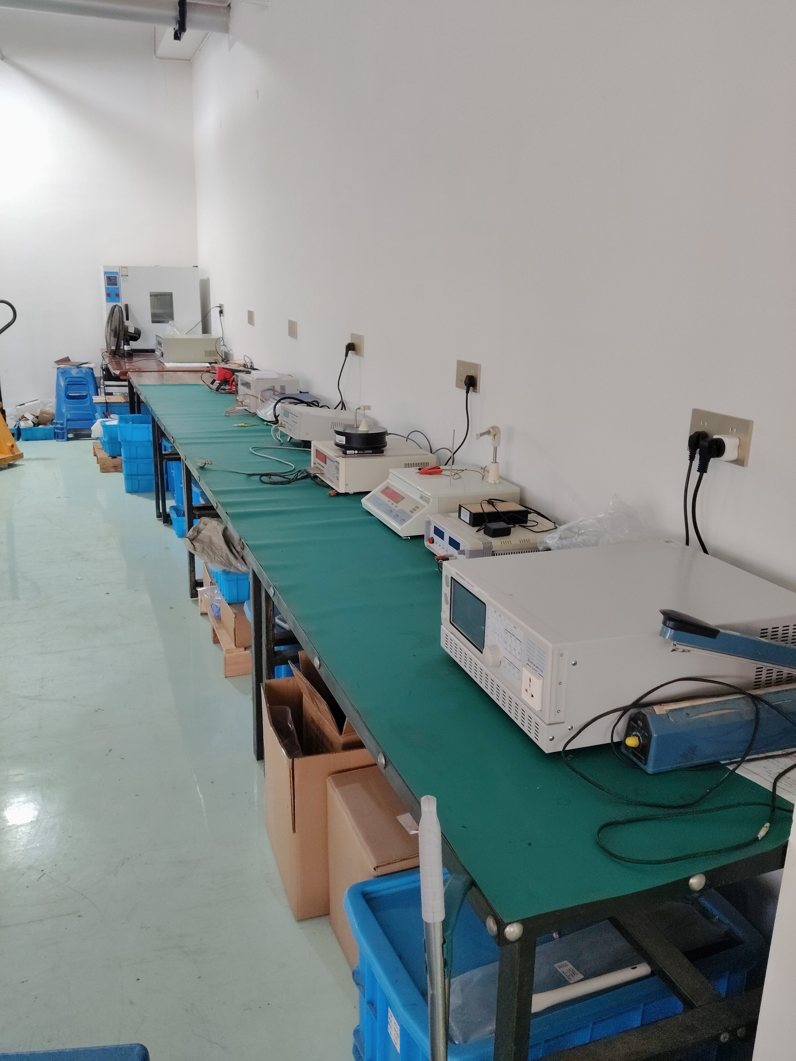
Routine testing and pre-shipment inspection on a current transformer assembly line.
For buyers who need the fuller technical and commercial picture before finalising a current sensing specification, HEYI Electrical's product brochure can be downloaded here: HEYI product brochure.
¿Tiene preguntas o necesita más detalles?
Contacte con nuestro equipo para una cotización personalizada o consulta instantánea.
Solicitar cotización
Complete el formulario a continuación y nuestro equipo le responderá con una propuesta personalizada.
Chat directo de WhatsApp
¿Prefiere chatear en tiempo real? Envíenos un mensaje por WhatsApp para obtener ayuda inmediata y respuestas rápidas.
- Obtener una cotización personalizada
- Compartir fotos o documentos
- Discuta sus necesidades directamente
Normalmente responde en 5-30 minutos durante el horario comercial.