
Fuse Switch Disconnector FAQ: Ratings, Materials and Installation
A technical and procurement reference for panel builders comparing Uimp, Ui, Ith, Ue and breaking capacity, material options, busbar spacing, and the NT/NH alternative.
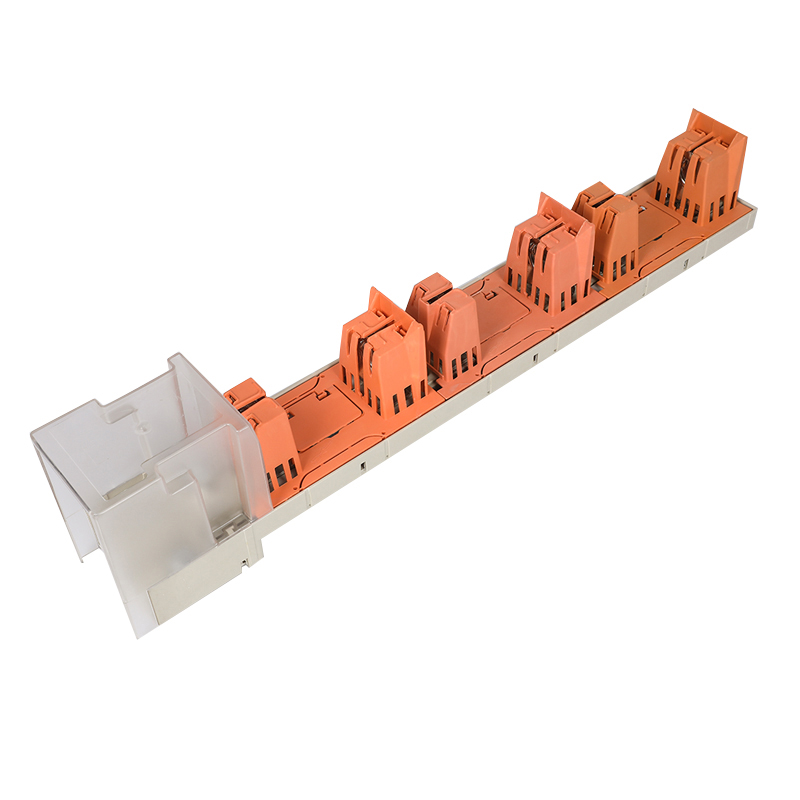
BTR2 stripe fuse rail: a 250–630 A fuse switch disconnector rated to 690 V AC, Ui 1000 V, Uimp 10 kV, IP30. Image: BARFUSE.
A low-voltage feeder pillar rarely fails acceptance because of the fuse. It fails because the disconnector would not fit the busbar spacing already drilled into the pan assembly, because IP30 was read as an outdoor rating, or because the insulation voltage on the nameplate was compared against the system voltage as if the two were the same number.
Fuse switch disconnectors carry four or five ratings that look interchangeable on a datasheet and behave very differently inside a panel. YUEQING BARFUSE ELECTRIC CO., LTD — trading as BARFUSE — is a Wenzhou-based manufacturer of low-voltage fuse switch disconnectors, busbar systems and distribution wiring management products, founded in 2014, with roughly 90% of output exported to the Middle East, Russia, Latin America, Central Asia, the EU, Africa and Oceania. Its BTR stripe fuse switch disconnector series, together with the NT/NH fuse base and BH DIN-rail fuse base ranges, provides a practical set of examples for the questions buyers ask most often.
The five ratings buyers confuse — and what each one actually constrains
Ue is the rated operational voltage at which the device is intended to switch and carry current. Ui is the rated insulation voltage, a design reference for clearance and creepage distances, and it is normally higher than Ue. Uimp is the rated impulse withstand voltage, describing the device's ability to survive defined transient overvoltages. Ith is the conventional free-air thermal current, the continuous-current basis the manufacturer declares. Breaking capacity describes the fault current the assembly can limit or interrupt when a compatible fuse link is fitted.
| Symbol | What it describes | BTR2 documented value | What it decides in procurement |
|---|---|---|---|
| Ue | Rated operational voltage | 415 / 500 / 690 V AC | Whether the device may be applied to the system voltage at all |
| Ui | Rated insulation voltage | 1000 V | Dielectric and clearance headroom above the operating voltage |
| Uimp | Rated impulse withstand voltage | 10 kV | Coordination with transient overvoltage and impulse category assumptions |
| Ith | Conventional free-air thermal current | 250 A / 400 A / 630 A | Continuous loading and cable or busbar sizing per feeder |
| Breaking capacity | Limiting short-circuit performance | 50–100 kA limiting short-circuit current | Whether the assembly suits the prospective fault level at the intake |
| Frequency | Rated frequency | 50 / 60 Hz | Suitability for 50 Hz and 60 Hz markets without re-qualification |
The practical rule is that Ue answers "may I install this here", while Ui and Uimp answer "how much margin does the insulation design carry". A buyer who treats Ui as an operating voltage will over-specify a 1000 V device for a 690 V system, while a buyer who treats Ue as an insulation rating may under-specify clearance in a panel with high prospective fault level.
BTR2 in practice: 690 V, 630 A, 10 kV and 50–100 kA
The BTR2 Stripe Fuse rail is documented at rated operational voltage 415, 500 or 690 V AC, conventional thermal current 250 A, 400 A or 630 A, rated insulation voltage 1000 V, rated impulse withstand voltage 10 kV, frequency 50/60 Hz and degree of protection IP30. It is built from copper, DMC, ABS and PC, and the series literature describes a hook-type busbar installation and an enclosed SMC结构 housing.
Read together, those numbers describe a specific application envelope. A 690 V AC system with a 630 A feeder sits comfortably below a 1000 V insulation rating, so clearance is not the constraint in a standard cubicle. The 10 kV impulse rating is the number to discuss with the panel designer when the board sits downstream of a transformer with limited surge protection. The 50–100 kA limiting short-circuit current is the number to compare against the prospective fault current at that point of the installation.
One procurement distinction matters here: the disconnector provides isolation and visible disconnection, while the fuse link provides the interruption. The product data states that this type of product requires supporting equipment such as fuses. The 50–100 kA figure therefore describes the behaviour of the disconnector-plus-link combination, and the fuse link rating used to support that statement should be confirmed in writing rather than assumed from the disconnector nameplate alone.
Across the wider BTR range the same rating pattern repeats with different material sets and switching options. Data for the BTR3, BTR4 and BTR6 describes simultaneous three-phase disconnection or independent single-phase disconnection, which is relevant for maintenance work on individual phases without isolating an entire board section.
Materials: where copper ends and DMC, SMC, ABS and PC begin
Material questions usually arrive as a single line in an RFQ — "what is the housing made of" — but the answer changes three different properties: conductivity, arc resistance and mechanical life. Copper carries the current, and the plating on it governs contact resistance over time. Thermoset moulding compounds such as DMC and SMC hold the geometry under heat and arcing. Thermoplastics such as ABS and PC are used where impact resistance, colour and moulding complexity matter more than arc resistance.
| Material | Typical role in fuse gear | Property that matters in procurement |
|---|---|---|
| Copper (often tin- or silver-plated) | Contacts, terminals and current path | Conductivity, contact resistance, corrosion behaviour at the joint |
| DMC (dough moulding compound) | Moulded insulation components | Tracking and arc resistance, dimensional stability under heat |
| SMC (sheet moulding compound) | Enclosed structural housing | Mechanical strength, flame-retardant behaviour, arc containment |
| ABS | Covers, handles and external parts | Impact strength, moulding accuracy, moderate heat tolerance |
| PC (polycarbonate) | Covers and transparent inspection parts | Higher impact and heat resistance than ABS, visual inspection |
Published composition differs by model, and that difference is worth capturing in a comparison sheet rather than treating "BTR" as one specification. BTR1 and BTR3 are documented as copper plus DMC. BTR5 is copper plus DMC plus ABS. BTR2, BTR4 and BTR6 are documented as copper plus DMC plus ABS plus PC. On the base side, the NT/NH fuse base uses a ceramic body with tin-plated copper contacts, the NT/NH fuse link uses ceramic with silver-plated copper, and the BH-400 DIN-rail fuse base specifies tin-plated copper contact material.
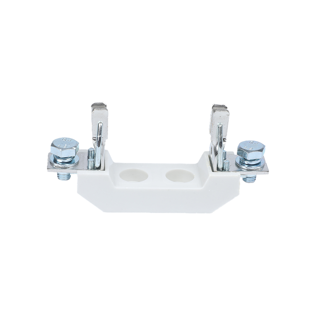
NT/NH fuse base (NT00, NT1, NT2, NT3): ceramic body, tin-plated copper contacts, rated up to 1140 V and 630 A, fuse link breaking capacity to 120 kA. Image: BARFUSE.
Busbar spacing, hook-type mounting and the 100 mm / 158 mm decision
Busbar spacing is the most common late-stage mismatch in LV panel projects, because the pan assembly is drilled before the fuse gear is ordered. The BTR2 series literature documents support for both 100 mm and 158 mm busbar systems, with a hook-type busbar installation that reduces the assembly step. Data for the BTR6 lists busbar distances of 100 mm and 185 mm, and industry technical references describe vertical fuse switch disconnectors as optimised for 185 mm and 100 mm systems generally.
The procurement consequence is straightforward: the spacing figure on the purchase order must match the drilled pan, not the preferred standard. A 158 mm rail will not seat on a 185 mm busbar pitch, and the 185 mm variant should not be assumed available across every current rating. Where the panel uses DIN-rail construction instead of busbar mounting, the BH-400 DIN-rail fuse base (690 V, 400 A, neutral links with 120 kA breaking capacity, IEC 60269-1 and 2, VDE 0636-1 and 2) covers that mounting method separately.
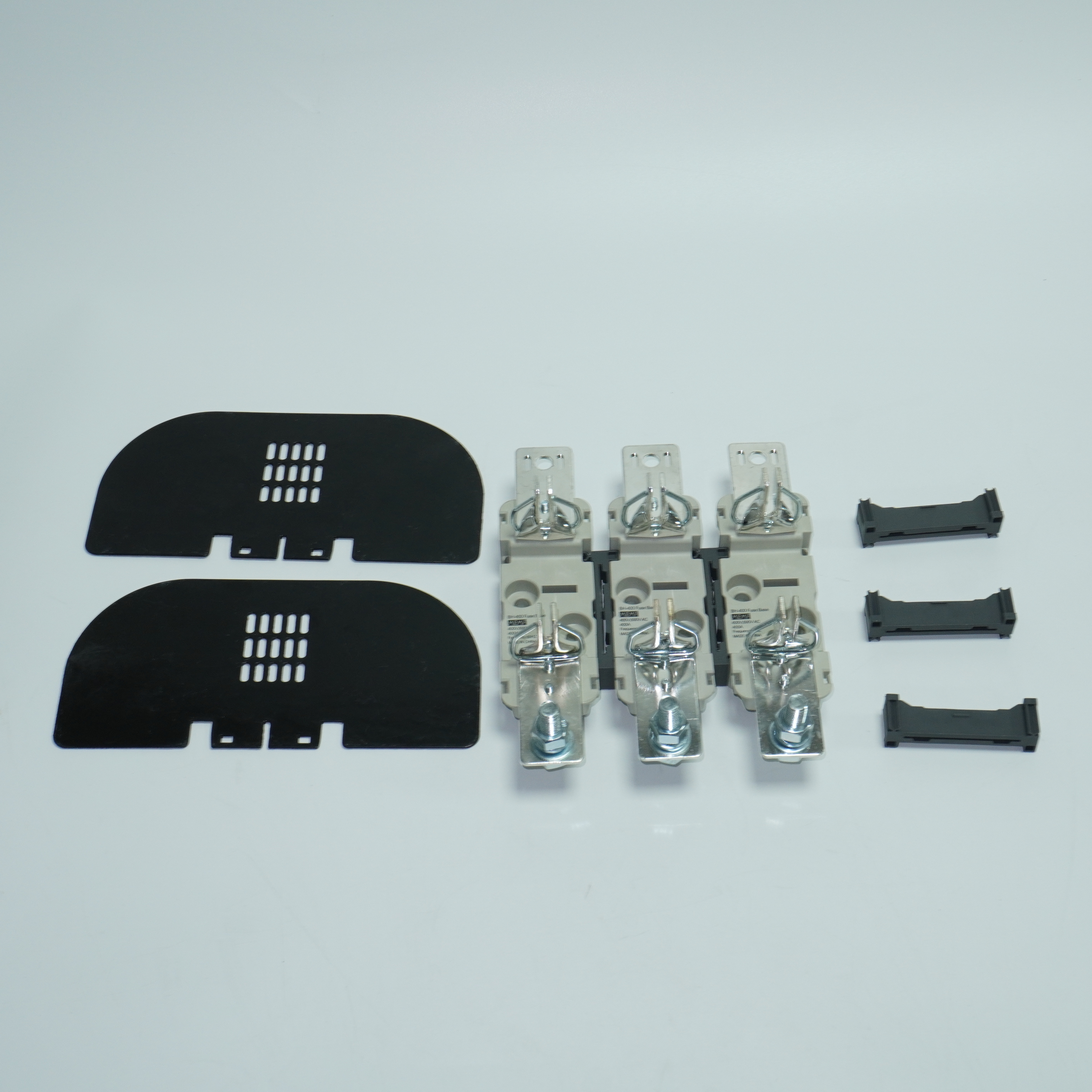
BH-400 DIN-rail fuse base: 690 V, 400 A, IEC 60269-1 and 2 / VDE 0636-1 and 2, tin-plated copper contacts. Image: BARFUSE.
IP30: what the second digit does not promise
IP30 protects against access to hazardous parts with a tool or finger and against solid objects above 2.5 mm. The zero in the second position means no water protection is declared. That is a real boundary, not a formality: a feeder pillar installed outdoors, exposed to driving rain or periodic washdown, cannot rely on IP30 alone. In those cases the protection comes from the enclosure, not from the fuse switch disconnector.
The same logic applies to conductive dust. A fine carbon or metal dust that settles inside a cubicle is a solid well below 2.5 mm and will pass an IP30 boundary. Panels in metallurgical, carbon-handling or heavy chemical environments typically need a filtered or sealed enclosure strategy, with the IP30 rating on the device treated as an installation assumption rather than a guarantee.
Stripe fuse switch disconnectors vs NT/NH fuse bases up to 1140 V and 630 A
These are two different product families solving two different problems, and the comparison only becomes useful when the voltage ceiling and the switching function are kept separate.
| Dimension | NT/NH fuse base (NT00, NT1, NT2, NT3) | Stripe fuse switch disconnector (BTR2 reference) |
|---|---|---|
| Rated voltage | Up to 1140 V AC | Ue 415 / 500 / 690 V AC |
| Rated current | Base up to 630 A; NT/NH links up to 1250 A | Ith 250 / 400 / 630 A |
| Breaking capacity | Fuse links to 120 kA | 50–100 kA limiting short-circuit current |
| Frequency | AC 50 Hz | 50 / 60 Hz |
| Construction | Ceramic body, tin-plated copper contacts | Copper, DMC, ABS, PC; enclosed SMC structure |
| Function | Fuse holder only — no switching or isolation | Integrated disconnection plus fuse protection |
| Standards referenced | IEC 269 as documented | IEC / EN 60269 (BTR6); VDE certification documented for BTR5 and BTR4 |
| Typical fit | Higher-voltage circuits up to 1140 V, panel designs already built around NT/NH links | 690 V systems needing feeder-level isolation on 100 mm or 158 mm busbar |
Three boundaries deserve to be stated plainly. First, the stripe fuse switch disconnector documented here tops out at 690 V AC operational voltage, so it is not a substitute for an NT/NH base in a 1140 V AC circuit, even though both families reach 630 A. Second, the disconnector requires compatible fuse links to deliver its stated short-circuit performance; it is not a self-contained protective device. Third, the disconnector is IP30 and built around 100 mm, 158 mm or 185 mm busbar pitches depending on model, so a retrofit into an existing panel with a different pitch or a harsher environment needs an adapter or enclosure solution rather than a like-for-like swap.
The reverse boundary is equally real. An NT/NH fuse base gives no visible isolation and no switching function, which means feeder-level maintenance on a base-only design depends on a separate switch or a withdrawable arrangement. Where the panel concept calls for visible disconnection at each feeder, the base alone will not satisfy the switching requirement regardless of its voltage headroom.
What changed in the standards, and what the market data suggests
IEC 60269-1:2024, published on 9 August 2024, updated the general requirements for low-voltage fuses and covers AC applications up to 1000 V and DC applications up to 1500 V. For buyers, the practical note is that the AC ceiling of the general standard and the 1140 V AC rating documented for NT/NH bases are not the same reference point. A specification above 1000 V AC should name the applicable standard edition and require the manufacturer's declaration for that rating rather than relying on a generic "IEC 60269" line in a quotation.
On the demand side, Fortune Business Insights projects the global electric fuse market at USD 5.84 billion in 2025, growing at a CAGR of 7.05% towards 2034. That figure should be read as directional rather than precise: published valuations for the same year range widely depending on whether fuse bases and switch disconnectors are aggregated with fuses or treated as separate mechanical switchgear. A panel builder's real signal is not the headline number but the mix — the same research landscape tracks a data-centre 800 V DC protection segment estimated at USD 265 million in 2026 with a 29.9% CAGR, a figure classified as medium confidence and best used to anticipate direction rather than to size a budget.
That direction matters for product selection because the AC ratings documented for the BTR stripe series, and the AC 50 Hz ratings of the NT/NH family, do not extend to DC photovoltaic or 800 V DC data-centre circuits. Buyers specifying DC fuse holders or photovoltaic fuse gear should not assume crossover from an AC datasheet; DC interruption behaves differently and requires its own qualification.
Where these products are actually installed
The documented application field for the BTR series and the NT/NH and BH ranges is the low-voltage distribution system in petroleum, chemical, metallurgical, power and construction industries, operating continuously with IP30 protection across a wide temperature range and requiring supporting fuses, flame-retardant housings and stable conductive performance.
Two company-reported cases illustrate how climate, rather than catalogue ratings, tends to drive the final specification. In Russia, a wholesaler supplied 7,000 units for electric power distribution over a five-year project, with the case record highlighting stable operation at low temperatures. In Saudi Arabia, an OEM electrical equipment manufacturer reports 300,000 pieces used for overload and short-circuit protection in low-voltage feeder pillars and distribution boxes over twelve years, with the case record citing 55 °C ambient resistance, salt-spray exposure, flame-retardant plastic parts and zero reported safety failures. A separate Saudi manufacturer case covers 600,000 pieces for feeder pillar applications over three to five years, with low temperature rise noted as the highlight.
These are supplier-side records, not independently audited field studies, and they should be weighed accordingly. Their procurement value is narrower but still useful: they indicate which environmental variables — low temperature, high ambient temperature, salt spray, continuous 24/7 duty — the manufacturer has already been asked to design against, which is a reasonable starting point for a project-specific technical discussion.
Procurement checklist before the purchase order
| Check | Why it fails in practice |
|---|---|
| Confirm system voltage against Ue, not Ui | Ui is an insulation reference; using it as an operating limit hides a 690 V ceiling |
| Match busbar pitch: 100 mm, 158 mm or 185 mm by model | Pans are drilled before fuse gear is ordered |
| State the fuse link used for the breaking-capacity claim | The disconnector depends on the link for interruption |
| Check Ith against continuous feeder loading | 250 A, 400 A and 630 A are not interchangeable frame sizes |
| Read IP30 as indoor-enclosure protection | No water protection is declared |
| Verify certification per model, not per brand | VDE coverage is documented for specific models such as BTR5 and BTR4 |
| Confirm material set for the exact model | BTR1 and BTR3 are copper plus DMC, while BTR2, BTR4 and BTR6 add ABS and PC |
| Confirm DC or PV circuits require separate qualification | Documented ratings are AC 50/60 Hz |
Future outlook
Three forces are likely to shape LV fuse gear specifications over the next procurement cycles. The first is standards drift: the 2024 revision of IEC 60269-1 widened the DC scope of the general low-voltage fuse standard to 1500 V, which pushes manufacturers to document AC and DC performance separately rather than in one combined line. The second is DC demand from data centres and photovoltaic distribution, visible in the 800 V DC protection segment tracked by commercial research. The third is documentation quality: as more panels are assembled from components sourced across several countries, the buyer's real risk shifts from product capability to specification traceability.
For a manufacturer such as BARFUSE, whose production is oriented toward export markets and whose quality system is supported by KEMA (DEKRA) and VDE testing accreditations alongside CB and SAA certification, that third force is the one that decides repeat orders. A 10 kV impulse rating and a 1000 V insulation rating are only useful to a buyer if they can be matched to a model number, a busbar pitch and a fuse link in a single document.
Frequently asked questions
What is the difference between Ue and Ui on a fuse switch disconnector?
Ue is the rated operational voltage at which the device is intended to carry and switch current; on the BTR2 it is documented as 415, 500 or 690 V AC. Ui is the rated insulation voltage, a reference for the insulation design and clearance distances; on the same product it is 1000 V. The operational voltage decides whether the device may be installed on a given system, while the insulation voltage describes margin above that operating point.
What does a 10 kV Uimp rating protect against?
Uimp is the rated impulse withstand voltage, describing the transient overvoltage level the device is designed to withstand without insulation failure. The BTR2 and several other BTR models are documented at 10 kV, while the BTR6 literature states a 12 kV impulse voltage. This rating is relevant to coordination studies, particularly where the panel sits downstream of a transformer with limited surge protection.
Can a 690 V stripe fuse switch disconnector be installed in a 1140 V system?
No. The BTR2 series is documented at a maximum rated operational voltage of 690 V AC, while NT/NH fuse bases are documented for circuits up to 1140 V AC. Both families reach 630 A, so current rating alone does not make them interchangeable. Circuits above 690 V AC require a product family whose operational voltage covers that level.
Does IP30 allow installation in an outdoor feeder pillar?
IP30 declares protection against access to hazardous parts and against solid objects above 2.5 mm, with no water protection. Outdoor installation therefore depends on the enclosure rather than on the device rating. The same applies to fine conductive dust, which passes an IP30 boundary and requires a filtered or sealed enclosure strategy.
How do I choose between 100 mm and 158 mm busbar spacing?
Choose according to the drilled pan assembly, not by preference. The BTR2 literature documents support for 100 mm and 158 mm busbar systems with a hook-type busbar installation, while BTR6 data lists 100 mm and 185 mm distances. Because the spacing options are model-specific, the pitch should be confirmed against the exact model number before the order is released.
At 630 A, should a panel use an NT/NH fuse base or a stripe fuse switch disconnector?
The decision turns on voltage and switching function rather than current. An NT/NH base reaches 1140 V AC and 630 A but provides no switching or visible isolation. A BTR2 disconnector offers integrated disconnection and 50–100 kA limiting short-circuit current at 690 V AC, but requires compatible fuse links and cannot be applied above its operational voltage. Requirements needing both 1140 V and feeder-level isolation must be resolved with a different product combination.
Are BTR products certified for export markets?
Certification is documented per model. The BTR5 Stripe Fuse rail is covered by VDE certification applicable to the global market, and BTR4 is documented as VDE-certified in the manufacturer's whitepaper material. The company also reports KEMA (DEKRA) and VDE testing accreditations together with CB and SAA certification, and operates an ISO 9001 quality system. The scope of any certificate should be checked against the specific model and destination market.
What customization is available for OEM panel builders?
Documented customization options include colour, logo, material, new design, surface treatment, mould development and packing, under OEM or ODM arrangements. The stated minimum order quantity is 5 pieces with a lead time of 30–45 days, 100% testing, and remote technical support after delivery.
The BARFUSE product catalogue, covering the BTR stripe fuse switch disconnector series, NT/NH fuse bases and links, and the BH DIN-rail fuse base range, is available as a PDF: Barfuse Catalogue.
¿Tiene preguntas o necesita más detalles?
Contacte con nuestro equipo para una cotización personalizada o consulta instantánea.
Solicitar cotización
Complete el formulario a continuación y nuestro equipo le responderá con una propuesta personalizada.
Chat directo de WhatsApp
¿Prefiere chatear en tiempo real? Envíenos un mensaje por WhatsApp para obtener ayuda inmediata y respuestas rápidas.
- Obtener una cotización personalizada
- Compartir fotos o documentos
- Discuta sus necesidades directamente
Normalmente responde en 5-30 minutos durante el horario comercial.