
FreeScan Trak ProW in Thailand: A Metrology 3D Scanner Case
Mould and tooling measurement problems rarely begin with accuracy alone. They begin with access, geometry and time: a cavity with deep ribs, a die insert that has run thousands of production cycles, a welded frame assembled from custom profiles. Those are not features a caliper can describe, and they are slow to verify on a coordinate measuring machine (CMM) when the surface is freeform.
A Thailand-based industrial machinery manufacturer that builds high-precision moulds and customised industrial equipment works with exactly this pattern. The company runs a FreeScan Trak ProW metrology 3D scanner for dimensional inspection on its own shop floor, and the system has been in service for more than a year.
This article examines what that deployment involves in practice: why marker-free scanning and wireless operation matter in a mould shop, what changes technically when optical tracking replaces reference markers, where the configuration fits and where it does not, and how a buyer at the evaluation stage should weigh it against traditional measurement methods.
Why Mould Inspection Becomes the Bottleneck in Custom Machinery Manufacturing
3D inspection is a non-contact, high-precision measurement process that captures the full geometry of a physical object using 3D scanning technology. By comparing the scanned data with the original CAD model, manufacturers can detect dimensional deviations, assembly defects, warpage and deformation. That definition describes a different category of measurement from the one most mould shops start with.
A caliper measures the distance between two points. A metrology 3D scanner captures millions of data points per scan across a surface, and it does so without touching the workpiece. For a mould cavity, a core insert or a die face — surfaces defined by draft angles, radii, parting lines and blended curves — the difference is coverage, not convenience.
Three pressures push mould and tooling inspection toward full-field measurement:
- Freeform geometry. A two-point check can confirm a dimension but cannot describe a contour. Deviation on a curved cavity wall is invisible to it.
- Wear over time. A production mould changes after thousands of cycles. Comparing a used tool against its original CAD reference requires data dense enough to show gradual material loss at radii and shut-offs.
- Reconfiguration cost. A custom machinery manufacturer rarely inspects the same part twice, so any measurement setup that depends on dedicated fixturing carries a repeated cost.
The underlying application mix is stable rather than seasonal. Reverse engineering dominated the 3D scanning application market in 2024, according to Grand View Research, driven by product redesign and legacy part digitisation — a description that fits custom mould and equipment work closely.
What the Thailand Manufacturer Needed From a Measurement System
SHINING 3D's published scanner selection guidance filters decisions in a defined order: object size first, accuracy requirements second, operational factors third. Applied to this deployment, the requirement list looked like this.
| Decision factor | Requirement in this shop | Why it drove the choice |
|---|---|---|
| Object size | Medium to large moulds, mould bases and custom equipment frames | Portable, reconfigurable scanning suits parts that cannot be moved to a fixed measurement station |
| Accuracy tier | Metrology-grade tolerance for cavities and die surfaces | Mould work sits in the band where certified, traceable accuracy is a qualification requirement |
| Marker handling | Minimum surface preparation on functional mould surfaces | Reference markers on a cavity can interfere with inspection, and large parts may need dozens to hundreds of them |
| Mobility | Free movement around a mould that stays on the bench or machine | Cable management around a large workpiece slows an operator in a working shop |
| Environment | Variable lighting, dust, and the wide temperature and humidity range typical of an industrial floor | Blue laser light is relatively insensitive to ambient light and surface reflectivity, which suits industrial inspection conditions |
| Software workflow | CAD comparison, deviation analysis, GD&T evaluation and reporting | Inspection output has to be usable by the quality team, not only by the scanning operator |
| Traceability | Acceptance testing against recognised standards | SHINING 3D scanners provide inspection reports and calibration certificates traceable to VDI/VDE 2634 and ISO 10360, with calibration and verification performed in an ISO/IEC 17025 accredited accuracy laboratory |
Two of those factors — marker handling and mobility — are usually where a mould shop's shortlist narrows. Together they point toward optical tracking rather than a fixed or tethered handheld configuration.
The Deployed System: FreeScan Trak ProW on a Working Shop Floor
SHINING 3D is a 3D vision technology company established in 2004 and headquartered in Hangzhou, China, with subsidiaries in Stuttgart, Barcelona, California, Florida and Tokyo, and in-house development of high-precision 3D vision hardware and software spanning metrology, professional and entry-level scanning. Its own selection guidance places the FreeScan Trak ProW+ among the systems recommended for heavy-industry and civil-aviation quality control work.
In the Thailand deployment, three characteristics of the tracking configuration carry most of the operational value.
Marker-free scanning
FreeScan Trak-style systems use built-in video photogrammetry (VPG) to track the scanner's spatial position continuously, so coded markers are not required. For a mould shop this changes the job before scanning starts: the operator does not have to cover a cavity or die face with targets, and inspection can begin shortly after the part is positioned.
Wireless operation
Wireless tracking removes the cable between the scanner and the tracking system, which is what allows an operator to walk around a large mould or a welded equipment frame without managing a tether. SHINING 3D's documentation is explicit on a point buyers frequently raise: wireless connectivity handles only data transmission and does not affect accuracy. In wireless mode the system requires a Wi-Fi router, which is included with the package; a wired connection remains available as an alternative.
One-unit deployment
The tracking architecture is designed so that one system covers more than one scanning task: the tracker can also be used independently as a large field-of-view handheld laser scanner. A shop that would otherwise need separate instruments for large mould bases and for smaller inserts can deploy a single unit and switch modes. SHINING 3D lists this detachable, multi-role design among its technical differentiators, alongside wireless operation, standalone inspection modules and intelligent self-positioning.
Scope note. The configuration, accessory set and software modules used by any individual scanner are confirmed at the point of purchase. Buyers evaluating the FreeScan Trak platform should confirm the exact model specification, delivered accessories and applicable calibration documents with the manufacturer or its local partner rather than relying on general product-family descriptions.
The detail a description cannot substitute for is duration. The Thailand system has now been in service for more than a year. Industrial-grade reliability is what makes that meaningful: compared with entry-level and consumer 3D scanners, industrial-grade equipment is designed to deliver more stable long-term performance, and SHINING 3D products require less repair and maintenance than alternatives, supported by a global service network. In metrology, a scanner that drifts or needs frequent intervention is not only an accuracy problem — it is a scheduling problem for the whole quality function.
Technical Explanation: What Marker-Free Tracking Actually Changes
To understand why marker handling dominates mould inspection scheduling, it helps to look at how scanning data is stitched together.
3D scanning integrates optics, mechanics, electronics and algorithms to capture the spatial structure and dimensions of an object. The process relies on stitching data from markers, features or textures, and those stitches introduce small errors. The errors accumulate, and the accumulation becomes significant when the object is several metres across. This is why photogrammetry is introduced into high-accuracy 3D scanning: scale bars and targets are imaged from multiple angles to build a high-accuracy reference framework that controls global accuracy across a large part.
Video photogrammetry (VPG) is the newer form of that idea. Instead of relying on hundreds of static images, it uses continuous video capture, and it eliminates the need for coded markers while still constraining volumetric accuracy. In practice the difference shows up in preparation time. SHINING 3D's analysis of scanning efficiency notes that on large projects operators may need to place dozens or even hundreds of markers to establish tracking references — and on objects such as vehicle bodies or construction machines, marker placement can take longer than the scanning itself.
Volumetric accuracy is the metric that governs whether any of this is acceptable in metrology. It describes measurement accuracy across a whole scanning volume rather than at a single point. A scanner specified as 0.02 mm + 0.015 mm/m, for example, is expected to hold within roughly 0.05 mm across a 2-metre object. Cumulative error grows with size; the tracking and photogrammetry layer is what keeps it bounded.
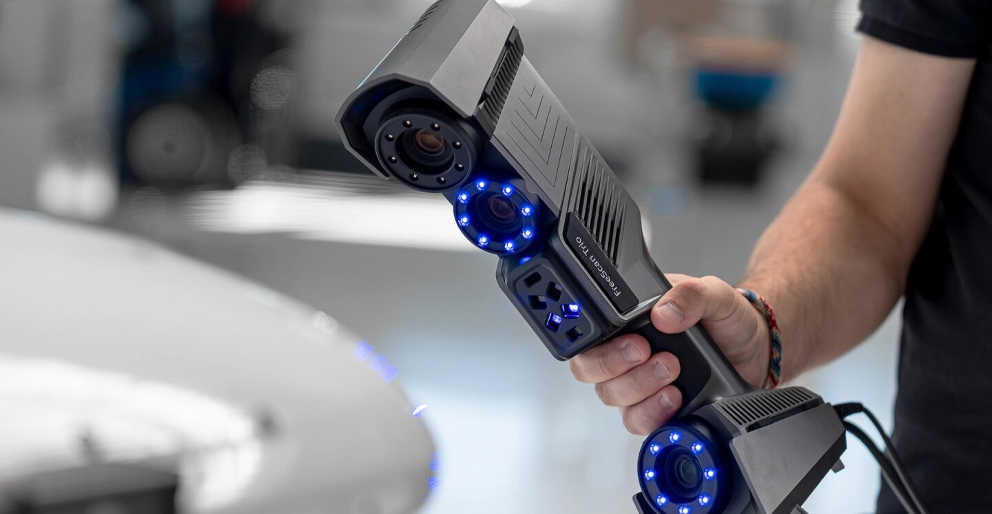
Light source choice follows the same logic. Blue laser is relatively insensitive to ambient light and to surface reflectivity, which is why it is used for industrial inspection and high-accuracy applications; infrared VCSEL scanning is better suited to rapid capture of large components. A tracking system able to switch between modes covers both the large mould base and the fine insert within the same job.
One boundary is worth stating plainly. Marker-free operation is the default, not an absolute rule: for very large surfaces, markers may still be recommended to ensure optimal accuracy. A shop scanning a multi-metre structure should confirm the reference strategy for that specific part rather than assuming marker-free applies universally.
From Scan to Inspection Report: the Workflow Around the Scanner
The scanner is one stage of a longer process. A professional 3D inspection workflow supports the full sequence from data acquisition to a traceable report:
- 3D data acquisition. The scanner captures complex geometries, freeform surfaces and detailed features that are difficult to measure with traditional methods.
- Data processing and alignment. Point cloud and mesh data are optimised, cleaned and aligned before analysis.
- CAD comparison, deviation analysis, dimensional inspection and GD&T evaluation. Scanned data is compared against the CAD reference, and 3D colour maps make surface differences visible. Geometric dimensioning and tolerancing analysis verifies critical dimensions and tolerance requirements.
- Report generation. Measurement results, deviation information and analysis data are organised into professional reports for review and documentation.
Software is where a scanner's specification turns into throughput. SHINING 3D's stated advantage in this area is specific: metrology software combined with industrial-grade reliability provides higher efficiency and accuracy in measurement tasks. In a mould shop, that translates into fewer manual measurement steps per part and a shorter cycle from scan to a quality decision.
Application Fit: Where This Configuration Earns Its Place
A tracking configuration of this type is well matched to a defined set of tasks: full-field inspection of injection moulds and die-casting moulds, including wear monitoring against the original CAD reference and verification after repair; first article inspection of welded frames, fabricated structures and machine assemblies measured in place; and reverse engineering of legacy parts when original design data is unavailable.
It also suits large mould bases and heavy tooling, where volumetric accuracy over a large measurement volume matters more than sub-micron point performance, and shop-floor quality control, where inspection happens next to the machine rather than in a separate controlled environment.
The same review should identify where the configuration is not the right answer. If the requirement is micro-detail on small precision parts — a sealing surface on a tiny insert, an engraving, a fine groove — a fixed blue structured-light scanner such as the OptimScan Q12/Q9 HD, with accuracy down to 0.004 mm in its small range, is the appropriate instrument. If a component contains deep holes, narrow gaps or hidden blind spots, a laser will not reach them; a portable probe is the practical complement. And where a single dimensional check on a simple part is all that is needed, a caliper remains far cheaper.
Market Trends Shaping Mould Shop Metrology
The global 3D metrology market was valued at USD 11.13 billion in 2024 and is projected to reach USD 15.01 billion by 2029, according to MarketsandMarkets. Grand View Research estimated the global 3D scanning market at USD 4.28 billion in 2024, with laser scanners accounting for 45.3% of total revenue — the technology family used for handheld and tracking inspection. Hardware remains the dominant revenue segment: scanners and CMMs accounted for 66.7% of total 3D metrology revenue in 2023, per Grand View Research.
Demand is concentrated where tolerances are tight. The automotive sector represented the largest end-user segment for 3D scanning in 2024, using scanners for in-line inspection and reverse engineering, according to Precedence Research; and EV battery-pack tolerances as tight as 0.025 mm are pushing automakers to replace manual gauges with automated optical scanners, per Mordor Intelligence. Those pressures propagate into the tooling supply chain, which is where mould makers sit.
Reading market figures carefully. Published market sizes in this category depend heavily on how the boundary is drawn. Estimates for 2024 range from about USD 1.98 billion (Precedence Research, 3D scanner market) to USD 4.28 billion (Grand View Research, 3D scanning market) to USD 11.13 billion (MarketsandMarkets, total 3D metrology including software and services). None is wrong; they measure different scopes. When a vendor quotes a market number, the definition matters more than the headline.
Standards are moving in parallel. VDI/VDE 2634 Part 3 is the primary standard for evaluating the accuracy of optical 3D measuring systems based on area scanning — the category that includes tracking and handheld scanners — while ISO/IEC 17025 accreditation is a critical verification requirement for any laboratory publishing 3D scanner accuracy data. For a mould shop buying on tolerance, those two references are the difference between a specification sheet and an auditable measurement.
FreeScan Trak ProW Compared With Traditional Mould Measurement Methods
| Method | What it captures | Relative speed | Best fit | Main constraint |
|---|---|---|---|---|
| Caliper / manual gauge | Discrete point-to-point dimensions | Baseline | Simple dimensions, quick checks on accessible features | Cannot describe contours; a small number of points leaves shape deviation undetected |
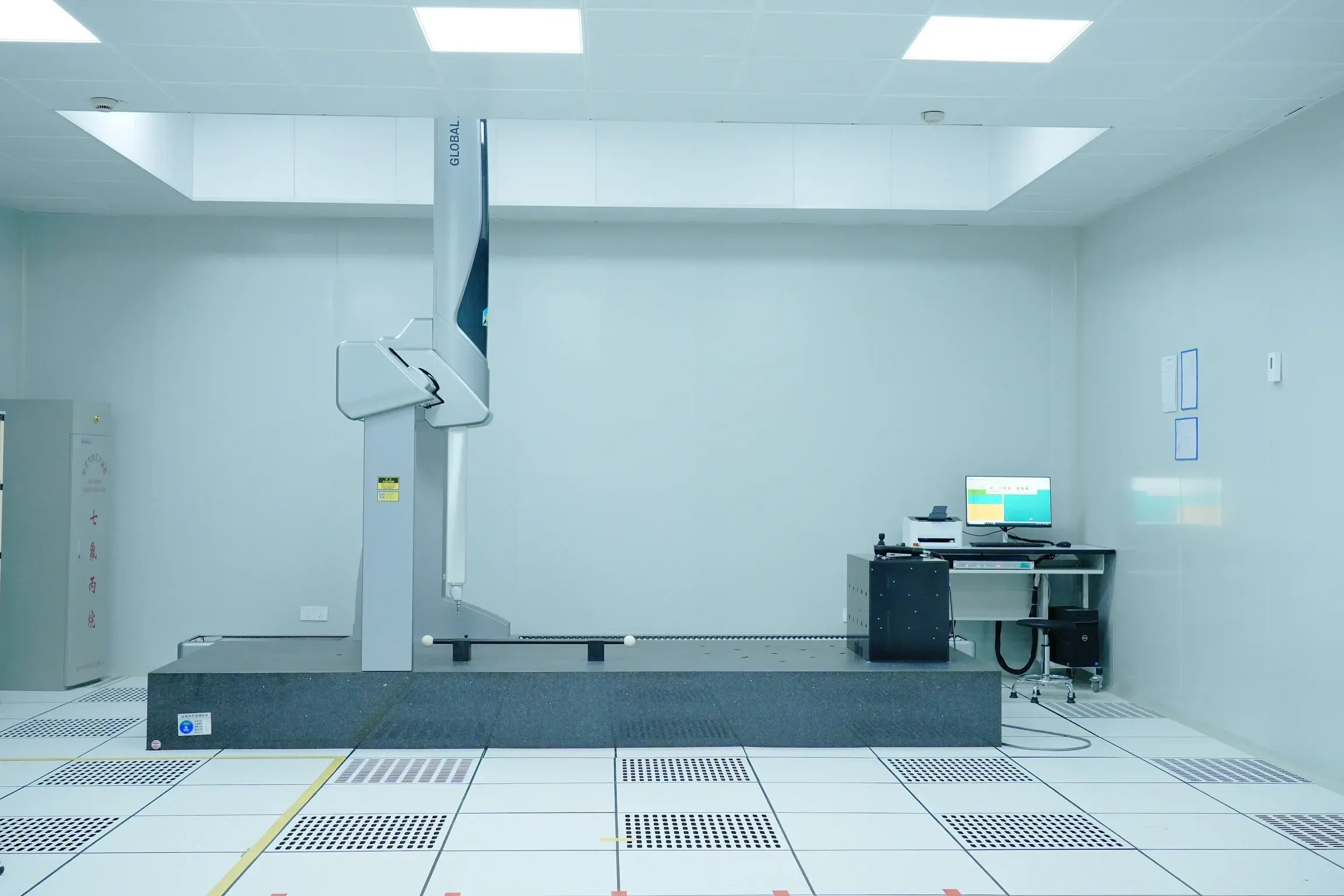
| Coordinate measuring machine (CMM) | Discrete probing points | Slower for many inspection tasks | High-accuracy verification of defined features | Requires dedicated infrastructure and part transport; complex freeform surfaces are harder and slower to evaluate |
| Handheld metrology 3D scanner | Full-field surface data, millions of points per scan | 5-10x faster than a caliper for full-surface work | Complex freeform surfaces, in-line inspection, reverse engineering, shop-floor quality control | Requires line of sight to the surface; needs calibration and appropriate conditions for precision work |
| Tracking metrology 3D scanner (FreeScan Trak configuration) | Full-field surface data with tracked, marker-free positioning | Comparable to handheld, with reduced preparation time on large parts | Large moulds, mould bases, welded frames, in-place inspection | Wireless mode requires a router; markers may still be recommended on very large surfaces |
SHINING 3D's own comparison material frames the optical-scanning case against CMM in measurable terms: faster measurement, greater flexibility, full-field 3D data capture and easier inspection of complex surfaces, with measurement speed up to 5-10 times faster for many inspection tasks — capturing millions of points in seconds instead of discrete probing points. The same material cites lower equipment and installation cost, less dedicated infrastructure, and inspection labour cost reductions in the range of 30-50%. Against entry-level and consumer 3D scanners, the stated difference is measurement accuracy up to 2-5x higher, better repeatability, stronger environmental adaptability, metrology software and industrial-grade reliability.
Those figures describe a category comparison, and they come with real boundaries. The first is cost: relative to a caliper, an industrial 3D scanning system is substantially more expensive, and the value case rests on full-surface inspection rather than on replacing every gauge in the shop. The second is measurement discipline — precision measurement generally requires calibration and controlled conditions. The third is optical access: tracking and laser scanning both need a line of sight, so deep pockets and internal channels need a different tool or a probe. A buyer who cannot state which of these constraints applies to their own parts is not yet ready to compare specifications.
Future Outlook
Wireless industrial scanning has moved through three identifiable stages: external Wi-Fi hub plus PC, built-in Wi-Fi module plus PC, and fully standalone all-in-one scanners that integrate wireless, computing and a display so that scanning and data processing both happen on the device. SHINING 3D positions itself at the third stage with products such as FreeScan Omni, EinScan Libre, EinScan Rigil and EINSTAR Vega, with FreeScan Omni adding on-device inspection capability. For a mould shop the trajectory matters less for novelty than for what it removes: fewer dependencies on a tethered computer, shorter setup, and inspection results available closer to production.
Two other developments are likely to shape the next procurement cycle. The first is automation — fixed and tracking scanners now integrate with robotic inspection systems for path teaching, automated measurement and report generation, shifting repetitive batch inspection away from manual operation. The second is digital quality records: automated reporting connects engineering and quality teams and supports continuous manufacturing improvement, which is where data captured over a one-year deployment starts to compound in value.
For the Thailand manufacturer, the outcome of the first year is less about a single scanner than about a repeatable process. Mould geometry that previously could only be confirmed by sampling points can now be compared to CAD as a whole surface, and the same scan data can serve reverse engineering and documentation. That is the practical meaning of a metrology 3D scanner moving onto the shop floor: measurement stops being a separate stage and becomes part of how the part is made.
FAQ
What makes a metrology 3D scanner suitable for mould inspection rather than for general scanning?
Mould inspection is a dimensional task, so the scanner has to produce data that can be compared against CAD and defended in a quality system. That requires certified, traceable accuracy, acceptance testing against standards such as VDI/VDE 2634 Part 3 and ISO 10360, and dense full-field coverage so freeform surfaces can be evaluated rather than sampled. General-purpose scanning tools can capture shape, but metrology-grade systems add the traceability, repeatability and inspection software that a quality function requires.
How much preparation time does marker-free scanning remove from a mould inspection job?
The saving depends on the part. Tracking references are normally established by placing markers on or around the workpiece, and SHINING 3D's own analysis notes that large projects may require dozens or even hundreds of markers, with marker placement on objects such as vehicle bodies or construction machinery sometimes taking longer than the scan itself. Video photogrammetry eliminates coded markers while maintaining volumetric accuracy, so preparation shifts from applying and later removing targets to simply positioning the part. On very large surfaces, markers may still be recommended for optimal accuracy, so the benefit is greatest on medium and large parts with accessible geometry.
Does wireless operation reduce measurement accuracy?
No. Wireless connectivity handles only data transmission and does not affect accuracy; the measurement chain is unchanged whether the scanner is connected wirelessly or by cable. In wireless mode the system requires a Wi-Fi router, which is supplied with the package and can be replaced by a customer's own router, and a wired connection remains available as an alternative. The practical considerations are environmental — signal conditions on a congested shop floor — rather than metrological.
How does a tracking 3D scanner compare with a CMM for mould and die work?
The two address different constraints. A CMM measures defined features by contact probing with high accuracy, but it requires dedicated infrastructure, the part generally has to be brought to the machine, and complex freeform surfaces are slower to evaluate. Optical 3D scanning captures full-field surface data non-contact, with measurement speed up to 5-10 times faster for many inspection tasks, and it is better suited to complex freeform surfaces, large parts, rapid inspection, in-line inspection and shop-floor quality control. Where the question is full-surface conformity of a mould, scanning is usually the more informative method; where a small number of critical dimensions must be probed to a very tight tolerance, a CMM remains appropriate.
What should a buyer verify before committing to a tracking 3D scanner?
Four items are worth confirming in writing. First, the accuracy specification that applies to your part size — volumetric accuracy matters more than a single-point figure when moulds are large. Second, the traceability documentation: calibration and verification should be performed in a laboratory operating in accordance with ISO/IEC 17025, with inspection reports and calibration certificates traceable to VDI/VDE 2634 and ISO 10360. Third, the software path from scan data to a report your quality team can issue, including CAD comparison and GD&T evaluation. Fourth, the boundary conditions for your specific parts — whether markers will be needed on the largest surfaces, whether deep pockets require a probe, and whether a fixed structured-light scanner is a better match for micro-features.
For readers who want the underlying capability documentation behind the systems referenced in this article, SHINING 3D's 3D digitizing introduction is available here: 3D Digitizing Introduction (PDF).