
EC Fan Acceptance Criteria: IP, ErP and Control Inputs
In data center cooling, an EC fan is accepted on three groups of model-specific evidence: the ingress protection stated for that model, the ErP operating point stated for that model, and the electrical and control interface stated for that model. Frame size, series name, and the fact that a similar part number performs well elsewhere in the building are context — not acceptance evidence.
The distinction matters because acceptance disputes rarely involve a fan that is obviously wrong. They involve a buyer treating a family-level assumption as a model-level fact: that a protection rating carries across a series, that a nominal voltage band means every voltage inside the band behaves identically, or that a control interface exists simply because the motor is electronically commutated. Each of those assumptions can be tested against a datasheet before a purchase order is issued, and should be.
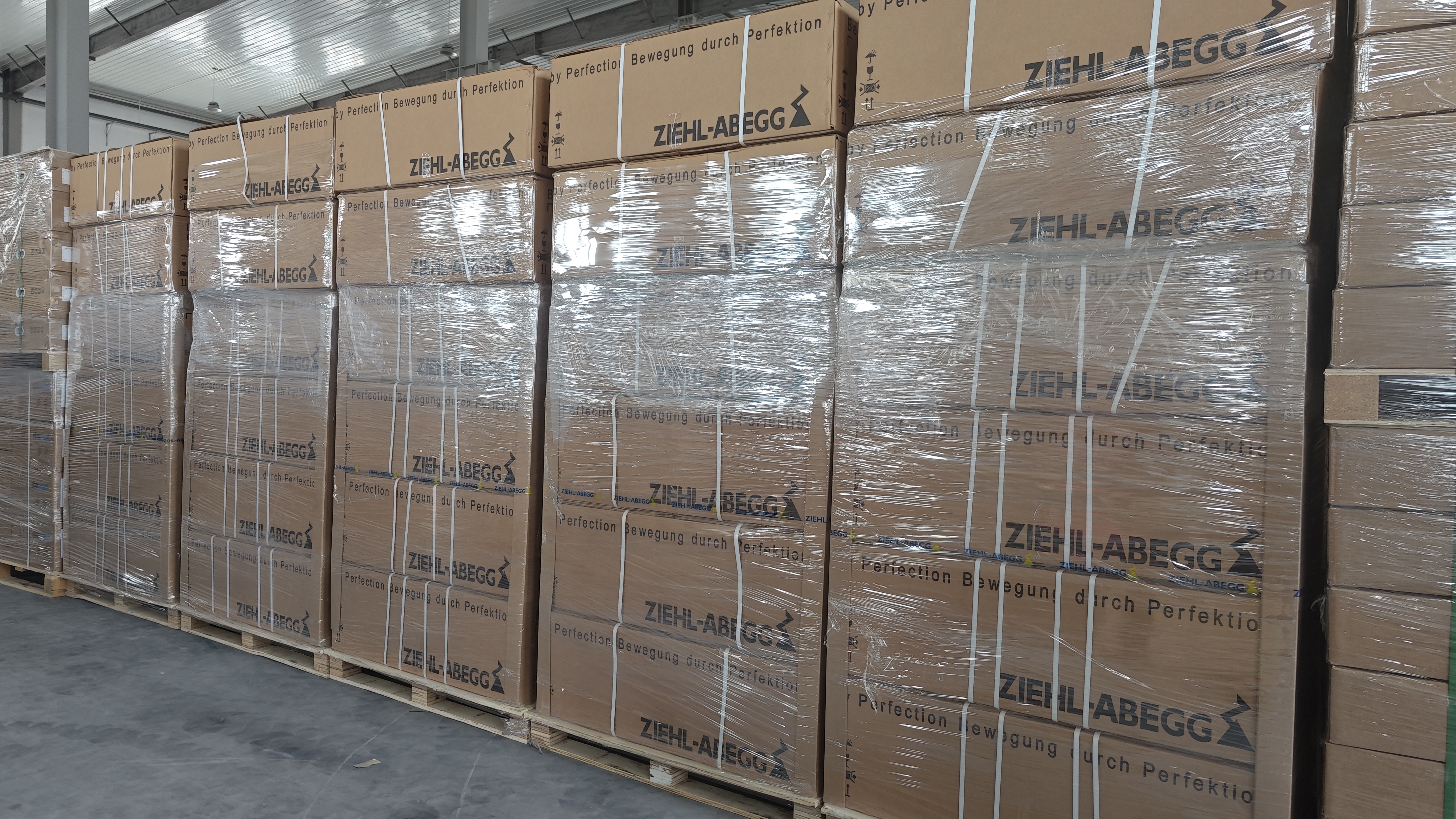
Why EC Fan Acceptance Became a Documentation Exercise
An EC fan integrates motor, electronic commutation and impeller into a single module. That integration is the reason it saves energy, and also the reason acceptance is no longer limited to airflow and a visual check. When the fan is the control device as well as the air mover, the buyer has to accept electronics behaviour, enclosure protection and communication interface at the same time.
Regulation has reinforced the shift. Regulation (EU) 2024/1834 applies from 24 July 2026 and sets stricter efficiency thresholds for fans from 125 W to 500 kW. The four centrifugal models discussed in this article are rated between 2,950 W and 5,700 W — comfortably inside that band — so declared operating-point data and rated power are no longer optional detail. They are the documents a project team is asked to produce when a fan selection is reviewed.
The practical consequence is straightforward: acceptance criteria should be written before the purchase order, not discovered at goods-in. Three criteria carry most of the weight in data center work — ingress protection, the ErP operating point, and the control input — with the electrical rating acting as the frame around all three.
Criterion 1: Ingress Protection Is a Model-Level Statement
The IP code describes two things. The first digit covers solid-particle protection; the second covers water. IP54 means dust-protected plus protection against splashing water. IP55 keeps the same dust protection and adds protection against water jets. The dust position is identical between the two; the water position is not.
This is where family-level assumptions cause trouble. The 310 mm backward-curved EC centrifugal fan family includes both ratings. K3G310-PV69-03 is stated at IP55. K3G310-PH58-02 is stated at IP54. Both are 310 mm units on a 3~380–480 VAC supply at 4,000 rpm, in the same power region — 3,050 W and 2,950 W respectively. A specification that reads "310 mm EC centrifugal fan, IP55" without a model number does not describe either unit precisely, and a supplier delivering the IP54 version against that wording has delivered a product that matches the description as written.
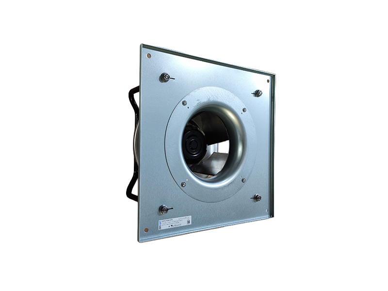
A second boundary is equally important. The stated IP rating describes the fan module as supplied. Once the fan sits inside a CRAH casing, an AHU section or an outdoor enclosure, the achievable protection of the assembled equipment depends on the housing, the gaskets and the cable entries — not on the fan alone. Acceptance records that treat the fan rating as the rating of the finished unit will be wrong, even when the fan is exactly as declared.
Criterion 2: The ErP Point Is One Operating Point, Not a Performance Envelope
An ErP operating point is a paired statement: airflow at a stated static pressure. It is the number against which a fan's efficiency-relevant behaviour is declared, and it is the number a buyer can compare between models without a laboratory.
Read four data points together and the logic of acceptance becomes visible:
- K3G500-PB33-01 — 500 mm, ErP point 10,945 m³/h at 1,245 Pa.
- R3G630-FB32-03 — 630 mm, ErP point 12,190 m³/h at 670 Pa.
- K3G310-PV69-03 — 310 mm, ErP point 4,020 m³/h at 1,583 Pa.
- K3G310-PH58-02 — 310 mm, ErP point 4,505 m³/h at 1,479 Pa.
The two 310 mm units show the pattern most clearly. The higher airflow figure, 4,505 m³/h, comes with the lower pressure figure, 1,479 Pa. The lower airflow figure, 4,020 m³/h, comes with the higher pressure figure, 1,583 Pa. Neither is better in the abstract. Which one should be accepted depends on the resistance of the actual air path — the filter class, the coil, the duct length, the plenum geometry.
The limitation is real and should be stated plainly: a declared operating point does not describe the shape of the fan curve, the part-load behaviour between full speed and minimum speed, the stall margin, or the acoustic output. If the datasheet provides only the ErP point, the acceptance record can only cover the ErP point. Part-load acceptance requires the full curve and supporting data, and a project that needs part-load evidence should ask for it at the specification stage rather than at commissioning.
Criterion 3: Voltage, Power and Current Form a Matched Set
Electrical ratings are only meaningful together. A voltage band without a power and current rating says little; a power rating without a speed reference says less. The table below consolidates what the four models actually declare.
| Model | Frame | Ingress protection | ErP operating point | Rated voltage | Rated power / current | Speed | Control stated |
|---|---|---|---|---|---|---|---|
| K3G500-PB33-01 | 500 mm | IP55 | 10,945 m³/h @ 1,245 Pa | 3~380–480 VAC | 5,700 W / 9.0 A | 2,250 rpm | EC stepless speed control |
| K3G310-PV69-03 | 310 mm | IP55 | 4,020 m³/h @ 1,583 Pa | 3~380–480 VAC | 3,050 W / 4.7 A | 4,000 rpm | Modbus and 0–10 V |
| K3G310-PH58-02 | 310 mm | IP54 | 4,505 m³/h @ 1,479 Pa | 3~380–480 VAC | 2,950 W / 4.6 A | 4,000 rpm | EC speed control, TOP thermal protection |
| R3G630-FB32-03 | 630 mm | IP55 | 12,190 m³/h @ 670 Pa | 3~380–480 VAC | 3,300 W / 5.1 A | 1,370 rpm | Modbus / 0–10 V, soft start, electronic protection |
The 3~380–480 VAC band is a permitted supply range, not a promise that airflow, power and current are unchanged at every voltage inside it. Rated power and rated current are declared at rated conditions. Acceptance therefore has two steps: confirm the site supply sits inside the stated band, and confirm the declared current is consistent with the protective device, cable sizing and upstream distribution that the project has actually installed. A current figure that does not fit the electrical design usually means the wrong model has been quoted, not that the datasheet is wrong.
Construction details belong in the same acceptance record because they affect how the fan behaves in service. K3G500-PB33-01 is stated with an aluminium impeller, galvanised steel support plate and inlet ring, and a die-cast aluminium electronics housing. R3G630-FB32-03 is stated with a PP plastic impeller and a die-cast aluminium electronics housing. Material differences of that kind influence weight, corrosion behaviour and how the impeller responds to sustained high static pressure — all relevant to whether the accepted fan suits the duty it was accepted for.
Criterion 4: Control Inputs Must Be Named, Never Inferred
Two fans can both be EC and still present completely different control surfaces. That is the single most common gap in data center fan acceptance, because "EC" describes the motor principle, not the interface.
The four models show four distinct positions:
- K3G500-PB33-01 is stated with EC stepless speed control, alongside integrated protection and communication.
- K3G310-PV69-03 is stated with Modbus and 0–10 V inputs.
- K3G310-PH58-02 is stated with EC speed control and TOP thermal protection.
- R3G630-FB32-03 is stated with Modbus and 0–10 V, soft start and electronic protection.
For a fan wall controlled from a building management system, the difference between "stepless speed control" and "Modbus plus 0–10 V" is not cosmetic. One route may be analogue at the panel; the other may be serial into the controller. The acceptance criterion is that the interface the project intends to use is the interface named on the model datasheet — and that the register map or the analogue scaling is confirmed from documentation rather than assumed to be common across the range. Soft start and electronic protection also affect how a parallel array stages up, so they belong in the acceptance record alongside the signal type.
Where the Ordering Route Fits: Hengrui EC Fan
Beijing Hengrui Hongsheng Mechanical & Electrical Equipment Co., Ltd. — trading as Hengrui EC Fan — is a Beijing-based supplier of ventilation, heat-dissipation and industrial control products, founded in 2011 and operating a 100,000 m² facility with approximately 700 employees, an 80-person engineering team and roughly 70% of volume exported, with the United States as its main market. The company holds long-term agent and distribution relationships with brands including ebm-papst and Ziehl-Abegg, and provides model selection and matching, technical service and full-category supply across EC centrifugal fans, EC axial fans, DC axial flow fans and blower fan ranges used in HVAC, data center, refrigeration and industrial applications.
For acceptance purposes the value of that position is continuity of model identity. A distributor's job in a qualified project is to keep the model number, the stated IP, the stated operating point and the stated control interface unchanged from submittal to delivery, and to supply the declaration data the acceptance record is built on. Where a project mixes models for different duties — a high static-pressure in-row unit alongside a high-airflow fan wall — the selection step is where the acceptance criteria are effectively set, because the choice of model determines which pressure point, which protection rating and which interface the project will later have to accept.
Stated supply terms include a minimum order quantity of 1 unit, a 7-day lead time, OEM production mode and 24/7 technical support.
The limitation should be stated as clearly as the capability. A distributor datasheet is a declaration, not a test report. If a project requires witnessed verification of airflow, input power or ingress protection, that is a separate scope requiring the appropriate test setup or third-party laboratory, and it is not implied by the supply relationship. Projects that need tested rather than declared values should budget for that scope at the specification stage.
Application: Matching the Acceptance Criteria to the Cooling Duty
Acceptance criteria only mean something when they are attached to a specific duty. In data center cooling the duties separate cleanly.
Fan walls and CRAH arrays at moderate resistance
R3G630-FB32-03 is stated at 12,190 m³/h at 670 Pa, 1,370 rpm, IP55, with Modbus and 0–10 V, soft start and electronic protection. That combination suits arrays where several fans in parallel share a comparatively low-resistance plenum and the airflow total matters more than the pressure ceiling. The 670 Pa point is the acceptance anchor: if the as-built plenum resistance is materially higher, the fan is being accepted against the wrong duty.
High-resistance CRAH and AHU sections
K3G500-PB33-01 is stated at 10,945 m³/h at 1,245 Pa, 2,250 rpm, IP55, with an aluminium impeller and EC stepless speed control. Here the pressure point is the reason to accept the model, not the airflow figure. Dense filtration, long duct runs and high-resistance coils are what justify the higher pressure declaration — and what make a lower-pressure fan unsuitable even if its headline airflow looks larger.
In-row and precision cooling in tight footprints
The 310 mm pair covers two different acceptance decisions rather than two quality levels. K3G310-PV69-03, at 4,020 m³/h and 1,583 Pa with IP55 and Modbus plus 0–10 V, fits high-resistance filtration in space-constrained cabinets. K3G310-PH58-02, at 4,505 m³/h and 1,479 Pa with IP54, offers more airflow at a lower pressure point and a lower protection class. Where the unit interior is already protected and IP54 is genuinely acceptable, that should be recorded as a deliberate decision — not discovered at goods-in as an apparent downgrade.
Outdoor heat rejection
Dry coolers and condenser-side applications move acceptance into a different regime. Axial EC fans such as W3G800-KU21-05, stated at 800 mm with IP55 and an ErP point of 19,455 m³/h at 247 Pa, are accepted on airflow at low resistance plus weather exposure, rather than on a high static pressure ceiling. The scenario is well defined in practice: cooling dry cooler coils using ambient cooling, and dissipating heat from air-cooled chiller condenser sides. High static pressure delivery through ductwork, by contrast, belongs to the centrifugal models above.
Comparison With Traditional AC and Belt-Driven Solutions
The comparison is not a simple upgrade narrative, because the acceptance burden shifts rather than disappears.
| Dimension | EC fan module | AC fan with external VFD / belt drive |
|---|---|---|
| Speed control | Integrated in the module; interface stated per model | External drive required; control lives in the panel |
| Wiring scope | Supply plus control signal | Shielded motor cable, drive panel, EMC measures |
| Protection rating | Stated for the fan module as supplied | Depends on motor enclosure, terminal box and installation |
| Part-load behaviour | Electronically controlled across the speed range | Limited by belt slip, pulley ratio and drive settings |
| Service model | Electronics integral to the fan; failure affects the module | Drive and motor replaceable as separate items |
| Acceptance evidence | Datasheet declarations: IP, operating point, control, electrical rating | Motor nameplate plus drive documentation plus site commissioning |
Three boundaries deserve emphasis. First, because the electronics are integral, a drive failure in an EC fan is a fan-level event rather than a control-panel event; projects that require field-replaceable drives as a resilience principle should acknowledge that they are trading that principle for integration simplicity. Second, the supply band is fixed — 3~380–480 VAC across these models — and a site outside it cannot be served by assumption. Third, the declared ErP point alone cannot demonstrate a part-load advantage over a belt-driven alternative; the curve is needed for that argument, and a high static-pressure model operated at low system resistance is being used away from the region it was selected for.
A fourth boundary applies to every EC fan in this article: the IP rating protects the fan, not the enclosure it is mounted in. A project that needs a protected air path has to accept the housing separately.
Market Trend: More Part Numbers, Tighter Declarations
The global EC fan market was reported at USD 3.5 billion in 2024, with a projected rise to USD 6.7 billion by 2030. Treat that figure as a directional market estimate from commercial research rather than a precise forecast; the direction, however, is consistent with what procurement teams already see in data center projects.
The supply side is contracting at the top while widening overall. ebm-papst Group reported sales of EUR 2.098 billion for the 2024/25 fiscal year, a 13.1% decrease year on year, and Ziehl-Abegg reported 2024 revenue of EUR 893 million, down 7% from EUR 955 million in 2023. At the same time, China's fan exports under HS 841459 reached 509 million units and USD 3.788 billion in 2024, up 6.96% in value. The practical reading for buyers is that more part numbers will reach more projects, while lead times and model continuity at the established tier deserve scrutiny. Model-level acceptance criteria are the filter that keeps a substitution from entering a qualified fan wall unnoticed.
Regulation adds a second pressure. With Regulation (EU) 2024/1834 applicable from 24 July 2026 for fans from 125 W to 500 kW, the declared operating point and rated power move from catalogue detail to procurement document. Buyers who already record them at acceptance will find compliance review largely administrative; buyers who do not will be reconstructing data after the fact.
Future Outlook
Three developments are reasonable to expect. Acceptance records will become structured data rather than scanned sheets, because the same fields — model number, IP, operating point, voltage, power, current, speed, control interface — are asked for by procurement, commissioning and, increasingly, efficiency review. Part-load evidence requests will rise as efficiency thresholds tighten, which will push curve data into the submittal package rather than the post-order conversation. And retrofit work, where fan walls replace belt-driven assemblies, will drive demand for as-declared comparison against installed duty, because a retrofit acceptance decision depends on knowing what the existing air path actually resists.
None of that changes the underlying rule. A fan is accepted on what is stated for that model, verified against what was delivered. Anything else is an assumption, and assumptions are what acceptance criteria exist to remove.
FAQ
What should an EC fan acceptance record contain for a data center project?
At minimum: the exact model number, the stated ingress protection, the stated ErP operating point as an airflow and static pressure pair, the rated voltage band, rated power and rated current, rated speed, and the stated control interface. Construction details such as impeller material and housing material are useful additions because they affect service behaviour. The record should reference the datasheet revision it was built from, so that a later delivery can be compared against the same baseline.
Does an IP55 statement for one model apply to other models in the same frame size?
No. Protection ratings are declared per model. Within the 310 mm backward-curved EC centrifugal family, K3G310-PV69-03 is stated at IP55 while K3G310-PH58-02 is stated at IP54, despite both being 310 mm units on a 3~380–480 VAC supply at 4,000 rpm in a similar power range. A specification that names a frame size and a rating but not a model number does not identify a single product.
What does the ErP operating point tell a buyer, and what does it not tell?
It states the airflow delivered at a specific static pressure — for example 10,945 m³/h at 1,245 Pa for K3G500-PB33-01, or 12,190 m³/h at 670 Pa for R3G630-FB32-03. It allows like-for-like comparison at declared conditions. It does not describe the full fan curve, part-load behaviour, stall margin or acoustic output. If those matter to the project, they have to be requested as separate data rather than inferred from the point.
Which control input should be specified for CRAH and fan-wall EC fans?
The one the installed controller can actually drive, named explicitly on the model datasheet. K3G310-PV69-03 and R3G630-FB32-03 are stated with Modbus and 0–10 V inputs; K3G500-PB33-01 is stated with EC stepless speed control; K3G310-PH58-02 is stated with EC speed control and TOP thermal protection. Where a serial interface is required, the register map has to be confirmed from documentation — it should not be assumed identical across models.
How should rated voltage, power and current be checked during acceptance?
Confirm that the site supply sits inside the stated band, which is 3~380–480 VAC for all four centrifugal models discussed here, and then confirm that the declared current is compatible with the protective device and cable sizing in the electrical design. Rated power and current are declared at rated conditions, so a mismatch between the declared current and the installed electrical design usually indicates a model or quotation error rather than a datasheet problem. The same logic applies to rated speed, which ranges from 1,370 rpm on R3G630-FB32-03 to 4,000 rpm on the 310 mm models.
What should happen if a delivered fan's datasheet differs from the approved submittal?
The difference should be treated as a deviation requiring a documented decision, not resolved informally on site. The relevant comparison points are the model number, the protection rating, the operating point, the electrical rating and the control interface. Where the deviation concerns protection class — an IP54 unit delivered against an IP55 requirement, for example — the decision should record whether IP54 is acceptable for that specific installation, since the fan rating and the assembled equipment rating are separate questions.
¿Tiene preguntas o necesita más detalles?
Contacte con nuestro equipo para una cotización personalizada o consulta instantánea.
Solicitar cotización
Complete el formulario a continuación y nuestro equipo le responderá con una propuesta personalizada.
Chat directo de WhatsApp
¿Prefiere chatear en tiempo real? Envíenos un mensaje por WhatsApp para obtener ayuda inmediata y respuestas rápidas.
- Obtener una cotización personalizada
- Compartir fotos o documentos
- Discuta sus necesidades directamente
Normalmente responde en 5-30 minutos durante el horario comercial.