
DXT30U(2+2)-F(B) vs 90A UAV Connectors: A Buyer Comparison
A UAV battery interface is a set of constraints before it is a component. Continuous current, conductor gauge, allowable temperature rise, pin count, ingress protection and mating durability move together: raise one and the others usually have to move as well.
This independent buyer comparison places the DXT30U(2+2)-F(B), a 2+2 power-signal composite lithium battery connector, against a 90 A continuous DC connector option used in agricultural and multi-rotor UAV battery links. The two share more than buyers expect. Both are rated DC 500 V, both operate across −20 °C to +120 °C, and both are specified for at least 1,000 mating cycles. They are nevertheless built for different aircraft classes, and the decision between them usually turns on harness architecture, sealing and inrush behaviour rather than on which datasheet carries the larger current figure.
Both products sit in the portfolio of AOYG DC Power Connector (www.aoygvn.com), a manufacturer and solution provider focused on high-current DC connection systems for lithium-ion smart devices, operating under an IATF16949:2016 automotive quality management system and reporting an annual output of 900,000 units.
What each connector actually is
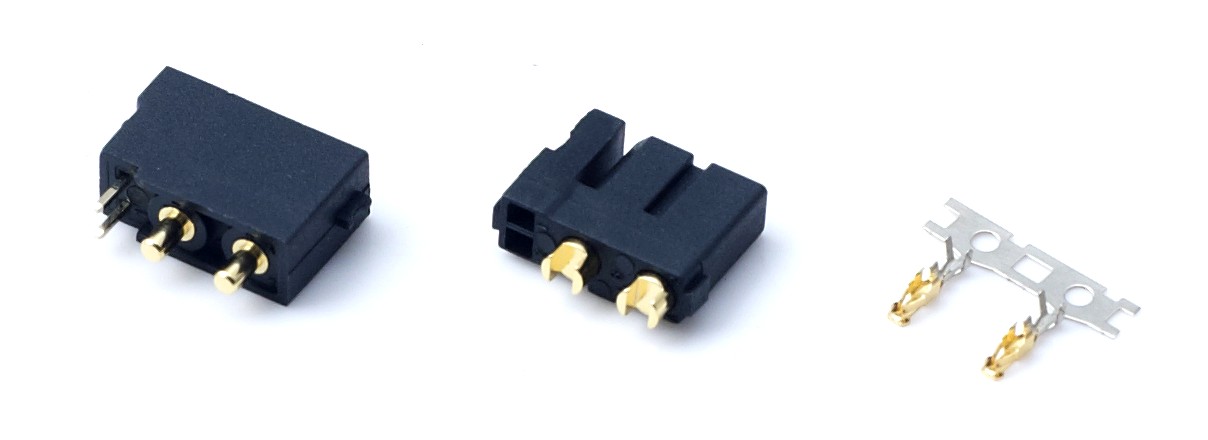
The DXT30U(2+2)-F(B) is a cable-soldered female connector carrying two power contacts and two signal contacts inside one black PA66 UL94 V-0 housing. Its rated voltage is DC 500 V. Continuous current is 20 A per power pin on 16 AWG wire, the signal pins are rated at 1 A, and short-term peak current is 35 A. Contact resistance is specified at ≤1.2 mΩ and insulation resistance at ≥2000 MΩ. The connector is rated IP40, works from −20 °C to +120 °C, accepts 12–16 AWG silicone wire, and is tested to a 48-hour salt spray regime. It mates with the DXT30U(2+2)-M and DXT30U(2+2)P counterparts and includes an anti-misplug structure to prevent reverse insertion.
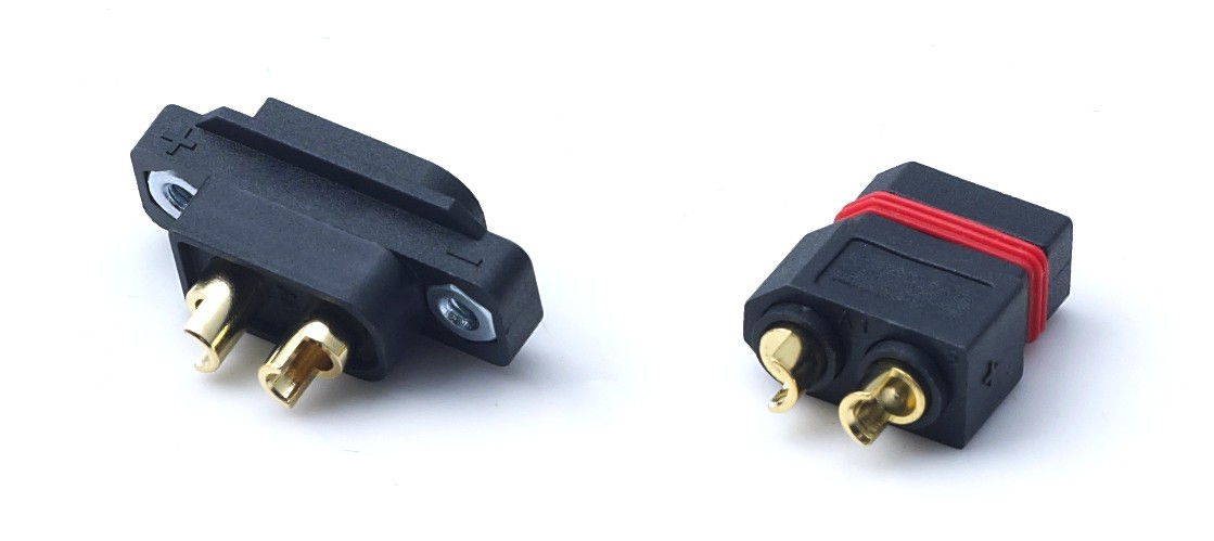
The 90 A option in this comparison is the DXT90H-M / DXT90S-F pair: a reinforced bare male connector and an anti-spark bare female connector. Rated voltage is DC 500 V. Continuous operating current is 90 A on 10 AWG wire with a temperature rise of no more than 85 °C, and short-term peak current reaches 120 A. The terminal is a 4.5 mm gold-plated banana plug, the housing is PA66 UL94 V-0, the operating window is −20 °C to +120 °C, protection class is IP40, and mating life is specified at ≥1,000 cycles. The female half contains a built-in pre-charge resistor with a two-stage contact design.
The problem: a large amp rating answers a question you may not be asking
Procurement teams commonly shortlist high-current DC power connectors by the biggest number on the front page. That number is conditional. A 90 A continuous rating exists only in combination with the specified conductor — here 10 AWG flexible cable, compatible with 8 AWG — and a defined temperature-rise ceiling of ≤85 °C. Change the wire, the crimp, the ambient temperature or the duty cycle and the practical ceiling moves.
On a small UAV or RC model, that headroom is often unusable. Airframe mass, internal volume and harness count are the binding constraints. A 4.5 mm banana terminal pair sized for 90 A adds material that a 12–16 AWG pack does not require, while the sensing and control lines still have to be routed somewhere.
The opportunity created by the 2+2 architecture is therefore architectural rather than electrical. Two power contacts and two signal contacts share one shell, so a sensing or control signal can travel through the same mating interface as the power path. Fewer separate connectors means fewer solder joints, fewer strain points and less internal wiring volume — a real advantage in space-constrained lithium-battery equipment.
Reading the two datasheets side by side
Continuous versus peak
The DXT30U(2+2)-F(B) carries 20 A continuously per power pin and 35 A at peak. The 90 A pair carries 90 A continuously and 120 A at peak. Peak figures describe short transients, not a duty cycle, and they should never be used to size a continuous load. The relevant comparison is the continuous column, read together with the wire gauge each figure assumes.
Contact resistance and temperature rise
The 2+2 connector publishes contact resistance of ≤1.2 mΩ. The same discipline is visible elsewhere in the range: ≤0.7 mΩ on the DXT30U-M/DXT30U-F drone connector, ≤0.8 mΩ on the IP67 DXT60EW-M+DXT60W-F waterproof model, and ≤1.0 mΩ on the DXT90H-M+DXT90E-F Yellow RC connector. The published specification for the DXT90H-M / DXT90S-F pair does not state a contact resistance figure. That is a due-diligence item, not an automatic disadvantage — but buyers comparing the two should request the value rather than assume parity, because two connectors with the same ampacity and different contact resistance produce different temperature rise at the same load.
Mating durability and corrosion
Both options are specified for at least 1,000 mating cycles and both rely on gold-plated terminals tested to a 48-hour salt spray regime, referenced to GB/T 10125 and ASTM B117 (neutral salt spray) and carried out by a third-party laboratory holding CNAS, CMA and ISO17025 accreditation. Salt spray performance matters most where the platform operates in coastal, agricultural or persistently humid conditions.
Anti-spark pre-charging
Inrush current is the most under-specified risk in battery connector selection. When a large-capacity lithium pack is connected live, the initial charging current of the input capacitors can arc across the terminals and progressively erode the plating. The DXT90S-F addresses this with a built-in pre-charge resistor and a two-stage contact sequence. The DXT30U(2+2)-F(B) datasheet does not list a pre-charge stage.
This is a design boundary rather than a defect. AOYG's own 60 A waterproof model, the DXT60EW-M+DXT60W-F, is explicitly documented as having no anti-spark structure, with a stated recommendation against live plugging and unplugging of large-capacity batteries. The lesson for buyers is straightforward: anti-spark is a deliberate feature to specify, not a property to assume.
Ingress protection
Both connectors in this comparison are rated IP40. That limitation deserves to be stated plainly: IP40 excludes water ingress protection. AOYG's UAV and RC application documentation describes IP40 as the standard protection level, with IP67 available on outdoor-oriented models. Within this range, sealed protection is delivered by models such as the DXT60EW-M+DXT60W-F, which uses a silicone O-ring and is rated IP67 at DC 500 V, 60 A continuous and 100 A peak, with contact resistance of ≤0.8 mΩ and compatibility with 8–10 AWG silicone wire.
Application fit: small UAV and RC versus agricultural and multi-rotor UAV
Where the DXT30U(2+2)-F(B) fits
The connector is specified for UAV, FPV drone, RC hobby model, light-duty e-bike, portable energy storage, robot, garden power tool, smart-device battery pack and BMS applications. In practice it suits space-constrained, weight-sensitive equipment where the pack's continuous discharge sits inside the 20 A per-pin and 35 A peak envelope, and where one or two sensing lines must travel alongside the power path. The series is compatible with cable-soldered male plugs as well as vertical-mount PB and horizontal-mount PW PCB headers, which gives designers some freedom over how the mating interface is anchored in the enclosure.
Where a 90 A connector fits
The DXT90H-M / DXT90S-F pair is aimed explicitly at agricultural drones, multi-rotor UAVs and LiPo battery power connection — platforms where continuous discharge is high enough that a single dedicated power connector is the only realistic option, and where flight vibration makes terminal stability the dominant failure mode. The male half uses thickened reinforced terminals for stable contact under continuous vibration, and the pair is dimensionally compatible with regular XT90 connectors, so an airframe designed around that footprint can move to a higher-current anti-spark version without structural modification. An optional strain relief cap is available to reduce cable breakage.
Compatibility is not a minor detail. Commercial market data published by ChinaHobbyLine in April 2026 identifies XT60 and XT90 as the primary industry standards for medium- to high-power non-proprietary RC aircraft and drone connections. Buyers evaluating a higher-current option generally want that footprint preserved rather than replaced.
Side-by-side comparison
| Parameter | DXT30U(2+2)-F(B) | DXT90H-M / DXT90S-F |
|---|---|---|
| Contact configuration | 2 power + 2 signal pins | 2 power contacts (4.5 mm banana) |
| Rated voltage | DC 500 V | DC 500 V |
| Continuous current | 20 A per power pin (16 AWG); 1 A signal pin | 90 A (10 AWG, temperature rise ≤85 °C) |
| Short-term peak current | 35 A | 120 A |
| Contact resistance | ≤1.2 mΩ | Not stated in published specification |
| Insulation resistance | ≥2000 MΩ | Not stated in published specification |
| Mating cycles | ≥1000 | ≥1000 |
| Protection class | IP40 | IP40 |
| Operating temperature | −20 °C to +120 °C | −20 °C to +120 °C |
| Housing / flammability | PA66 UL94 V-0, black | PA66 UL94 V-0 |
| Terminal material | H62 brass, gold-plated | Brass, gold-plated (0.3 µm standard) |
| Applicable wire | 12–16 AWG silicone wire | 10 AWG recommended, 8 AWG compatible |
| Anti-spark pre-charge | Not listed in published specification | Built-in pre-charge resistor in DXT90S-F |
| Typical application fit | Small UAV, FPV, RC models, robots, portable storage | Agricultural drone, multi-rotor UAV, LiPo battery link |
When integration, sealing or pre-charge outweigh raw ampacity
Buyers at the evaluation stage benefit from a short set of decision rules rather than a single headline number. The following criteria consistently separate the two architectures in real procurement discussions.
- Size to continuous current, not peak. A 35 A peak rating is not a 35 A duty rating, and a 90 A continuous rating is only available at the conductor gauge and temperature-rise condition the datasheet specifies.
- Count the harnesses your airframe actually needs. If a sensing or BMS line already exists as a separate run, the 2+2 removes a connector, a solder joint and a mounting point — a gain that rarely appears in an ampacity comparison.
- Treat ingress protection as a hard gate. Where the operating environment involves spray, pesticide mist, rain or wash-down, neither connector in this comparison is water-rated; the appropriate move is to an IP67 model such as the DXT60EW-M+DXT60W-F.
- Decide whether operators will connect live. If yes, anti-spark pre-charging should be a requirement, not a preference, and the connector should be selected accordingly.
- Verify contact resistance alongside ampacity. Lower contact resistance means lower temperature rise for the same load and a longer service life for the plating.
- Confirm the gauge assumption behind every current claim. 20 A per pin is stated at 16 AWG; 90 A is stated at 10 AWG with 8 AWG compatible.
- Check whether 1,000 cycles is enough. Both are rated ≥1000 mating cycles, so a difference in field life will come from wire routing, strain relief and environmental exposure rather than from the contact system itself.
Limitations buyers should accept before ordering
A comparison that only lists advantages is not useful for procurement. The boundaries of each option are as follows.
- DXT30U(2+2)-F(B) — sealing. Rated IP40. It provides no water ingress protection and should not be specified for exposed outdoor platforms without an additional enclosure strategy.
- DXT30U(2+2)-F(B) — current class. At 20 A per power pin and 35 A peak on 12–16 AWG wire, it sits below the current class of large agricultural multi-rotor packs.
- DXT30U(2+2)-F(B) — inrush. No pre-charge stage is listed in the published specification, so live mating of large-capacity packs should be avoided or handled by an anti-spark counterpart.
- DXT30U(2+2)-F(B) — signal headroom. Signal pins are rated 1 A. They carry sensing and control signals, not a secondary power load.
- 90 A pair — specified data gaps. Contact resistance and insulation resistance are not stated in the published specification and should be requested directly.
- 90 A pair — condition dependence. The 90 A continuous figure depends on 10 AWG wire and a temperature rise of no more than 85 °C, so termination quality directly determines whether the rating holds in service.
- 90 A pair — architecture. It carries no signal pins, so BMS or telemetry lines still require separate routing. It is also rated IP40, not sealed.
Market signals shaping this choice in 2026
Two published market data points frame the wider context. The global high power connectors market was valued at approximately USD 5.47 billion in 2025, according to Fact.MR. Separately, DC connectors represented 58.7% of the energy storage connector market in 2025, a share Dataintelo attributes to higher voltage requirements.
The pressure for higher current density is not limited to drones. A telecom site planning reference notes that 5G base stations consume two to three times more power than their 4G predecessors, with typical draws of 11.5 to 14 kW and peaks reaching 19 kW. That figure matters to UAV and RC buyers only indirectly — but it illustrates the same engineering direction: current demand is rising across low-voltage DC systems, and the response is load-matched connector selection supported by test documentation, not a single oversized part used everywhere.
Within the UAV and RC segment, the practical split appears to be widening rather than closing. Compact composite connectors serve weight- and volume-constrained airframes that need power and signal in one interface, while dedicated high-current connectors with anti-spark behaviour serve platforms where a single pack can deliver triple-digit current. Buyers who understand which group their platform belongs to will shortlist faster and rework less.
Due-diligence questions for purchasing, quality and housing compliance
The technical comparison narrows the field; the commercial and quality checks determine whether the chosen part arrives consistently. The questions below reflect the documentation AOYG states it maintains across its connector range.
Purchasing terms
- What minimum order quantity applies to a custom pin configuration versus a standard catalogue part? AOYG publishes an MOQ of 2 units and a lead time of 30–45 days.
- How are custom size, current specification, pin position, wiring structure and logo printing handled under the OEM/ODM scope, and does tooling or setup cost apply?
- What is the revision-control process if a specification changes after the sample is approved? The company supports customized production against customer drawings, samples and technical parameters.
- Which export markets are covered, and are shipping terms aligned with Europe, America and Southeast Asia distribution? The company reports those regions as its export markets.
Acceptance criteria and quality control
- Request the electrical performance test report, referenced to IEC 60512 and GB/T 5095, and confirm that the report covers the exact model being purchased, not only a family representative.
- Request the salt spray test report for the gold-plated terminal, referenced to GB/T 10125 and ASTM B117 and specified at 48 hours.
- Confirm RoHS 2.0 compliance under the IEC 62321 series and REACH SVHC compliance under Regulation (EC) No 1907/2006 and the ECHA SVHC Candidate List, both issued by a third-party laboratory with CNAS and CMA accreditation.
- Ask for the CE-LVD Declaration of Conformity under Directive 2014/35/EU and EN 61984 where the product is placed on the EU market.
- Confirm the manufacturing quality system: ISO 9001:2015 certification issued by a CNCA-accredited body, and IATF16949:2016 for the automotive-grade process controls applied across production.
- Clarify the inspection regime. AOYG states 100% testing, which should be defined in the purchase agreement — electrical continuity, contact resistance sampling, visual and dimensional checks, and lot traceability.
Technical matching support
- Can the supplier confirm that the mating counterpart, wire gauge and termination method in your design are compatible with the connector you are ordering? The 2+2 series mates with DXT30U(2+2)-M and DXT30U(2+2)P, and the 90 A pair is dimensionally compatible with regular XT90.
- Will the supplier provide the contact resistance figure that is missing from the 90 A pair's published specification?
- Is sample testing supported before mass production, and what documentation accompanies the sample?
Flame-retardant housing requirements
- Confirm the housing material in writing: PA66 with UL94 V-0 flame retardance, tested against the UL 94 standard for flammability of plastic materials.
- Verify that the declared operating range of −20 °C to +120 °C is supported by the housing and terminal combination, not by the terminal alone.
- Where the platform is deployed near lithium packs, treat the flammability rating as a safety parameter rather than a marketing line, and retain the test report with the purchase records.
Outlook
Three developments are worth tracking. First, composite power-signal connectors are likely to become more common where airframes are weight-sensitive, because consolidating power and sensing into one shell reduces both mass and assembly time. Second, anti-spark pre-charging is moving from a premium feature toward an expectation in the higher-current classes, since the failure mode it prevents — progressive terminal erosion from inrush arcing — is expensive to diagnose in the field. Third, sealing requirements are increasingly treated as a model-selection decision rather than a specification label, with buyers moving to IP67-rated parts when the operating environment demands it instead of assuming a standard connector will cope.
For buyers, the practical conclusion is unchanged: match the connector to the duty cycle, the conductor and the environment, and verify the supporting test documentation. Ampacity is one input into that decision, not the whole of it.
FAQ
What does the 2+2 designation on the DXT30U(2+2)-F(B) mean?
It describes the contact layout: two power contacts and two signal contacts inside one housing. The power pins are rated 20 A continuous on 16 AWG wire, the signal pins are rated 1 A, peak current is 35 A, and the rated voltage is DC 500 V.
Can a 2+2 composite connector replace a 90 A connector in a UAV?
Only where the pack's continuous discharge stays inside the composite connector's rated continuous current. The 2+2 connector is rated 20 A per power pin and 35 A peak, while the 90 A connector is rated 90 A continuous and 120 A peak on 10 AWG wire. The determining factors are duty cycle, conductor gauge and permissible temperature rise, not pin count.
Is the DXT30U(2+2)-F(B) waterproof?
No. It is rated IP40. AOYG's UAV and RC application documentation describes IP40 as the standard protection level with IP67 available on outdoor-oriented models. Sealed protection in this range is provided by products such as the DXT60EW-M+DXT60W-F, which uses a silicone O-ring and is rated IP67.
Which wire sizes are supported by each connector?
The DXT30U(2+2)-F(B) accepts 12–16 AWG silicone wire, with the 20 A continuous rating stated for 16 AWG. The 90 A connector recommends 10 AWG silicone cable and is compatible with 8 AWG, with its 90 A continuous rating tied to the 10 AWG condition.
Do both connectors support at least 1,000 mating cycles?
Yes. Both are specified at ≥1000 mating cycles, and both use gold-plated terminals that have passed a 48-hour salt spray test referenced to GB/T 10125 and ASTM B117.
Which certifications should a buyer verify before placing an order?
The relevant documents are ISO 9001:2015 and IATF16949:2016 for the quality system, the CE-LVD Declaration of Conformity under Directive 2014/35/EU and EN 61984 for EU placement, RoHS 2.0 under the IEC 62321 series, REACH SVHC under Regulation (EC) No 1907/2006, UL94 V-0 under the UL 94 standard, and the electrical performance and salt spray test reports under IEC 60512 / GB/T 5095 and GB/T 10125 / ASTM B117.
¿Tiene preguntas o necesita más detalles?
Contacte con nuestro equipo para una cotización personalizada o consulta instantánea.
Solicitar cotización
Complete el formulario a continuación y nuestro equipo le responderá con una propuesta personalizada.
Chat directo de WhatsApp
¿Prefiere chatear en tiempo real? Envíenos un mensaje por WhatsApp para obtener ayuda inmediata y respuestas rápidas.
- Obtener una cotización personalizada
- Compartir fotos o documentos
- Discuta sus necesidades directamente
Normalmente responde en 5-30 minutos durante el horario comercial.