
Copper Busbar Basics: Materials, Standards and Applications
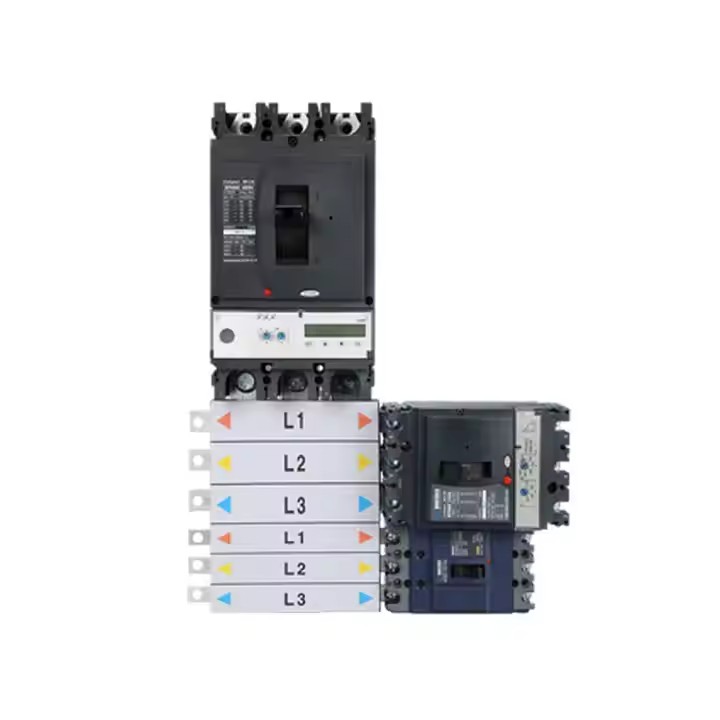
A copper busbar is a solid copper conductor that carries and distributes electrical current inside low-voltage switchgear, distribution boards and control panels. In day-to-day specification language the term covers a family of related components: comb busbars that link a row of miniature circuit breakers (MCBs), pan assembly busbars mounted behind moulded-case circuit breakers (MCCBs), chassis busbars, and terminal bars used for neutral or earth connections. Because one machined conductor replaces a set of individual cable runs, the busbar decision shapes how a board is assembled, inspected and maintained.
The commercial weight behind that technical description is straightforward. Precedence Research values the global busbar market at USD 19.83 billion in 2025, and the same source estimates that copper busbars accounted for 62.8% of the market by material in that year. Busbars are therefore not a peripheral accessory inside low-voltage distribution; they are one of its largest material categories.
Quick definition. A copper busbar is a rigid copper conductor — usually a flat bar or a machined profile — that distributes current inside an assembly. In low-voltage distribution it appears as comb busbars, pan assembly busbars for MCB and MCCB circuits, chassis busbars and terminal bars, and it is normally paired with insulating polycarbonate (PC) parts.
Why busbars moved earlier in the specification process
For most of the last three decades, the busbar was treated as a detail resolved after the breaker schedule was finalised. Conventional panel building connects breakers with insulated cable and lugs, which is flexible but creates a large number of individual terminations per board. Every termination is a point that has to be prepared, torqued, inspected and re-checked in service, and every cable run takes up routing space that a busbar does not need.
The opportunity offered by a pre-assembled busbar pan is geometric rather than promotional. The conductor thickness, the mounting plate, the phase spacing and the terminal geometry are fixed at the factory, so the panel builder's task shifts from forming and routing conductors to mounting the pan and connecting the breakers. Product documentation for this product family describes the intent in engineering terms: precise tooth pitch for reliable contact, standardised phase spacing to reduce wiring errors, a cleaner interior for visual inspection, and a one-click connection concept aimed at shortening installation time. Whether or not a specific project benefits depends on volumes, breaker choice and the number of ways required — but the direction of travel is clear, and it is why busbar questions increasingly arrive at the research stage rather than the purchasing stage.
Buyers researching this category typically need to resolve four things before they can compare offers at all: the conductor material, the rated current and the number of ways, the mechanical fit with the breakers they already use, and the compliance evidence the supplier can produce. Material and rating are the two that drive everything else.
Where Yueqing Barfuse Electric sits in the busbar supply chain
Yueqing Barfuse Electric Co., Ltd. is a Chinese manufacturer of low-voltage fuse switch disconnectors, busbar systems and high- and low-voltage distribution wiring management products, including MCB pan assemblies and MCCB pan assemblies. The company was established in 2014, is located in Wenzhou, Zhejiang Province, operates a manufacturing facility of 10,000 square metres, employs approximately 45 staff, maintains an R&D team of seven engineers, and reports an annual production capacity of around 250,000 units. Roughly 90% of its output is exported, and its markets include the Middle East, Russia, Latin America, Central Asia, the EU, Africa and Oceania, with a sales presence in more than 40 countries and regions.

Two capability facts matter more to a specifier than the headline capacity figure. First, the production workshop is organised around 6S management standards and uses over 30 sets of modern digital wire-cutting machines and punches — equipment whose relevance to busbars is direct, because conductor geometry and terminal pitch are cutting and punching tolerances. Second, the inspection chain includes a Rockwell hardness tester, an electric withstand voltage tester, a spring tester, a salt spray tester and a flame retardant tester, which covers conductor hardness, dielectric performance, spring and contact behaviour, corrosion resistance and flame-retardant behaviour of the insulating parts.
On the compliance side, the company is certified to ISO 9001 and holds testing accreditations from KEMA (DEKRA) in the Netherlands and VDE in Germany, as well as CB certification and SAA certification in Australia. The BP1 MCB pan assembly is listed in the product documentation with a DEKRA test certificate. OEM and ODM production services are offered, which means a buyer can work either from an existing catalogue configuration or from an in-house design.
How copper busbar ratings are actually determined
The current rating of a busbar is not a single number, and it is not determined by material alone. It is a function of conductor cross-section, the thickness available for the conductive path, the terminal interface, and the thermal behaviour of the complete assembly. Catalogue tables express the first of these variables directly.
Model BP4, an MCB pan assembly busbar used as a comb busbar in distribution boards, illustrates the relationship between thickness and current clearly: 125A at 2.0 mm conductor thickness, 160A at 2.5 mm, and 250A at 3.0 mm. The same pattern appears in the MCCB range. On model BP5, a two-pole MCCB pan assembly, the incoming ratings are 125A at 4 mm thickness, 250A at 6 mm and 400A at 10 mm, with outgoing ratings of 63A at 2 mm and 125A at 3 mm. In other words, a specifier cannot read the current rating off a model name; the thickness column carries the real information.
Terminal geometry is the second determinant. BP4 has an incoming terminal width of 20 mm and an outgoing terminal measuring 5 by 11 mm. BP6, a three-pole MCB chassis busbar rated at 250A, has an incoming terminal of 21 by 22 mm and an outgoing terminal of 6.5 by 12 mm. BP5 has a 25 mm incoming terminal width and a 15 mm outgoing terminal width. These dimensions decide whether the busbar physically accepts the breaker terminals a project already uses, and they are the reason two busbars with identical current ratings are not interchangeable.
Insulation is the third element. The conductive path is copper, while the case and insulating parts are polycarbonate (PC). On BP5, the design provides simultaneous disconnection of live and neutral conductors — a configuration detail that matters in circuits where isolation of both poles is required.
There is an important boundary here. A busbar's catalogue rating describes the conductor, not the finished board. Inside a real enclosure, the achievable current depends on the breakers used, the thermal environment, the enclosure itself and the assembly as tested. Buyers comparing two pan assemblies at the same nominal rating should treat the catalogue number as an input to the assembly design, not as a substitute for it.
Inside the pan assembly busbar family
Pan assembly busbars are usually grouped by the breaker type they serve and by pole configuration, which is where the common shorthand — SP, DP and TP pan assemblies — comes from. The table below sets out the configurations documented for this product range.
| Model | Configuration | Current ratings | Ways | Terminal geometry |
|---|---|---|---|---|
| BP1 | MCB 3P pan assembly (three-phase) | 125A, 160A, 250A | 6W–72W | Connect 2.0 x 5 mm; outline 2.0 x 20 mm; DEKRA test certificate |
| BP2 | MCB 2P modular pan assembly | 125A / 250A; 220/240/120V | Modular | Incoming 3 x 15 mm; outgoing 2 x 5 mm; double-pole MCB or RCBO outgoing; MCCB or MCB incoming |
| BP4 | MCB 1P pan assembly busbar (comb busbar) | 125A (T2.0 mm), 160A (T2.5 mm), 250A (T3.0 mm) | 4W–72W | Incoming width 20 mm; outgoing 5 x 11 mm |
| BP6 | MCB 3P chassis busbar | 250A | Customisable mounting plate | Incoming 21 x 22 mm; outgoing 6.5 x 12 mm; IEC 61439 and AS/NZS claimed |
| BP3 | MCCB 3P pan assembly | Incoming 250A, 400A, 630A, 800A; outgoing 125A, 250A, 400A | 2W–14W | Compatible with pole distances of 25 mm, 30 mm, 35 mm and 45 mm; OEM accepted |
| BP5 | MCCB 2P pan assembly busbar | Incoming 125A (T4 mm), 250A (T6 mm), 400A (T10 mm); outgoing 63A (T2 mm), 125A (T3 mm) | 2W–40W | Incoming 25 mm; outgoing 15 mm; for DP MCCB with 25 mm pole distance and 50 mm width |
Source: Barfuse product documentation. Ratings refer to the documented configuration of each model.
All models in the table are described as copper and PC constructions. Two structural observations follow from the range. The first is that the family spans a much wider current band than the individual models suggest — from 63A outgoing circuits to 800A incoming feeds — so a single board may reasonably combine a high-current MCCB pan assembly at the incomer with lower-rated MCB comb busbars on the branch side. The second is that the mechanical interface, not the electrical rating, is usually the limiting factor when a project changes breaker brand late in the design cycle.
Where copper busbars are used
The applications documented for this product family are industrial and commercial building electric management. The operating profile recorded in the application data is specific: indoor conditions, continuous 24/7 operation, a role of power distribution and circuit protection, and matched equipment consisting of circuit breakers. The stated requirements are multiple current specifications — 125A, 160A, 250A, 400A, 630A and 800A appear across the range — a high-conductivity copper busbar, reliable electrical conductivity, and ease of installation.
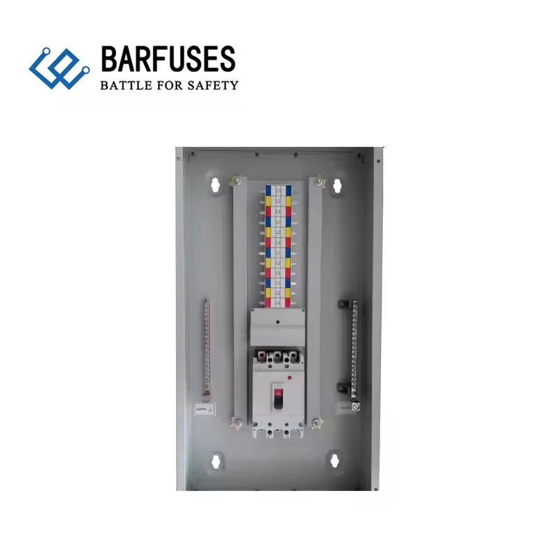
That profile explains why busbars appear in several different positions within the same installation. At the incomer, an MCCB pan assembly such as BP3 or BP5 handles the incoming feed. On the branch side, MCB comb busbars such as BP4 or BP1 distribute to a row of single- or three-pole devices. A chassis busbar such as BP6 provides a rigid mounting and connection structure where the mounting plate has to follow a specific outgoing MCB layout. Enclosure-level products follow the same logic: the DB01 distribution box combines a steel sheet body with a copper pan assembly busbar, supports incoming MCCB ratings of 250A, 125A or MCB 63A, and offers 2 to 32 ways with MCB branch protection; DB02 pairs a steel sheet body with a copper pan assembly busbar, supports incoming MCCB ratings of 800A, 630A, 400A, 250A and 125A with branch MCCB ratings of 400A, 250A and 125A, and covers 2 to 16 ways.
It is worth separating two different protection questions that buyers often merge. The busbar family described here is specified for indoor operation. Where ingress protection is required, that is an enclosure property rather than a conductor property — the DB13 waterproof low-voltage distribution box, for example, is rated IP65 with IK10 impact resistance, with an enclosure and door thickness of 1.2 mm to 1.5 mm and a 2.0 mm mounting plate. Choosing an IP-rated enclosure does not change the busbar rating inside it.
The application data for this product family lists usage across a wide set of markets, including Indonesia, Kuwait, Nigeria, Oman, Russia, Saudi Arabia, Thailand, Vietnam, Pakistan, the Philippines, Malaysia, Australia, Argentina, Chile, Colombia, Egypt, Turkey, South Africa, Kenya and India, among others. That geographic spread is consistent with the supplier's own export profile of roughly 90% of output shipped to more than 40 countries.
Market trend analysis
Three trends in the published busbar data are relevant to anyone specifying this category in the current cycle.
Copper remains the default, but it is no longer unchallenged. Copper busbars held 62.8% of global busbar market share by material in 2025 according to Precedence Research. The same source forecasts aluminium busbars growing at 6.9% CAGR between 2026 and 2035, and attributes that faster growth to lower weight and cost optimisation in large infrastructure projects. For low-voltage distribution boards, where conductor geometry is tight and space is limited, this does not displace copper — but it does mean material substitution is now a live conversation at the design stage rather than a purely academic one.
High-density applications are growing faster than the category average. Congruence Market Insights puts laminated busbar growth in high-density applications at 8.9% CAGR. Laminated busbars serve a different design problem from pan assemblies — very low-inductance, high-density power connections — but the direction is the same: more current in less space, with the conductor treated as an engineered component.
Supply remains concentrated, and standards are moving. China accounts for over 30% of global copper processing capacity and produces more than 11 million metric tons of refined copper annually, according to Congruence Market Insights. On the standards side, IEC 61439-6:2025, the part of the IEC 61439 series covering busbar trunking systems, carries an effective date of 1 December 2025. Pan assemblies are not busbar trunking systems, but the revision signals continued tightening of how low-voltage assemblies are verified — and BP6 already documents claimed compliance with IEC 61439 and AS/NZS in this product range.
Copper busbar systems compared with conventional cable wiring
A modular busbar pan is not automatically the better answer for every board. The comparison below sets out where the two approaches differ, and where the busbar approach runs into real limits.
| Dimension | Conventional cable and lug wiring | Modular copper busbar pan assembly |
|---|---|---|
| Number of terminations | Multiple per circuit; each one prepared, torqued and inspected | Brought down to the interfaces between busbar and breaker |
| Layout predictability | Depends on the individual installer | Fixed by factory geometry: tooth pitch, phase spacing, terminal width |
| Late design changes | Cable is re-routable and re-terminable on site | Lower — the pan is tied to a specific breaker model and pole distance |
| Inspection and maintenance | Requires tracing individual conductors | Physically visible; documented as a cleaner, more inspectable interior |
| Lead time | Standard cable available from stock | Custom configurations are built to order |
The limitations deserve to be stated plainly, because they are the reason some projects still use cable.
- Breaker compatibility is a hard constraint. BP3 is documented for MCCBs with pole distances of 25 mm, 30 mm, 35 mm or 45 mm, and BP5 is designed for a two-pole MCCB with a 25 mm pole distance and 50 mm width. A change of breaker brand or frame size after the busbar is specified requires a new pan, not an adjustment.
- Customisation is the norm, not the exception. Several models accept OEM configuration and mounting plates tailored to the outgoing MCB layout. That flexibility is real, but it means lead time and engineering effort scale with how far a project departs from a catalogue configuration.
- Indoor specification. The documented operating condition for this busbar family is indoor use. Outdoor or high-ingress installations need to solve the environment at enclosure level first.
- Copper is not the only material in play. Aluminium busbars are forecast to grow faster than the market average through 2035, and for weight- or cost-sensitive infrastructure the material trade-off may point away from copper.
- Market data on this category is approximate. Published 2025 busbar market estimates range from USD 15.72 billion (Stratview Research) to USD 20.3 billion (IMARC), with the difference attributed to whether locally custom-fabricated busbars are counted alongside factory-assembled systems. There is also no single HS code for pan assembly busbars; trade data is typically aggregated under HS 8537 for boards and panels, or HS 8544 for insulated conductors. Any figure quoted for this specific sub-category should be read as directional.
Future outlook
The next phase of this category is likely to be defined less by materials and more by configuration data. Because pan assemblies are customised components, the commercially useful question is not only how large the busbar market is, but which ways counts and pole configurations are actually being ordered, in which regions. That data is not currently available in a standardised form — it is the gap identified in the published research, which recommends tracking modular pan assembly configuration frequency as a dataset in its own right. Suppliers who can describe their configuration mix precisely will be easier for buyers to evaluate than suppliers who can only describe capacity.
Alongside that, three developments are worth watching. The aluminium growth forecast of 6.9% CAGR through 2035 suggests material selection will become an explicit line item in more specifications. The revision of IEC 61439-6 with a December 2025 effective date points to continued formalisation of how busbar systems are verified. And the higher growth rate recorded for laminated busbars in high-density applications indicates that the busbar concept keeps migrating into spaces where cable was once the only option.
For buyers at the research stage, the practical conclusion is unglamorous: material, thickness, terminal geometry, ways count and compliance evidence are the five variables that determine whether a copper busbar system fits a project, and all five are documented before price becomes a meaningful comparison.
FAQ
What is a copper busbar used for in low-voltage distribution?
A copper busbar distributes current inside a low-voltage assembly. In practice it appears in several roles: as a comb busbar linking a row of MCBs, as a pan assembly busbar mounted behind MCB or MCCB breakers, as a chassis busbar providing connection and mounting structure, or as a terminal bar for neutral and earth connections. Its documented function in these applications is power distribution and circuit protection, with circuit breakers as the matched equipment.
How is a busbar current rating determined?
Primarily by conductor cross-section and thickness, and secondarily by the terminal interface and the thermal behaviour of the finished assembly. Catalogue data shows the relationship directly: the BP4 MCB pan assembly busbar is rated 125A at 2.0 mm conductor thickness, 160A at 2.5 mm and 250A at 3.0 mm, while the BP5 MCCB pan assembly carries incoming ratings of 125A at 4 mm, 250A at 6 mm and 400A at 10 mm. The achievable rating inside a real enclosure also depends on the breakers, the enclosure and the assembly as tested.
Are copper or aluminium busbars more common?
Copper is the dominant material. Precedence Research estimates copper busbars held 62.8% of global busbar market share by material in 2025. The same source forecasts aluminium busbars growing at 6.9% CAGR from 2026 to 2035, attributing the faster growth to lower weight and cost optimisation in large infrastructure. Material choice therefore depends on the specific installation rather than on a single rule.
What is the difference between a comb busbar and a pan assembly busbar?
Both are copper busbar systems, but they serve different breakers and mounting arrangements. A comb busbar such as BP4 links a row of single-pole MCBs inside a distribution board and is available from 4W to 72W with ratings from 125A to 250A depending on thickness. A pan assembly busbar such as BP3 mounts behind three-pole MCCBs, supports incoming ratings from 250A to 800A and outgoing ratings from 125A to 400A across 2W to 14W, and is matched to breaker pole distances of 25 mm, 30 mm, 35 mm or 45 mm. A two-pole version, BP5, is designed for DP MCCBs with a 25 mm pole distance and a 50 mm width.
Which standards and certifications apply to busbar products?
Two levels apply. At product and assembly level, BP6 documents claimed compliance with IEC 61439 and AS/NZS, and the BP1 model is listed with a DEKRA test certificate. At system level, IEC 61439-6:2025 covers busbar trunking systems and carries an effective date of 1 December 2025. At supplier level, Yueqing Barfuse Electric Co., Ltd. is ISO 9001 certified and holds testing accreditations from KEMA (DEKRA) in the Netherlands and VDE in Germany, plus CB certification and SAA certification in Australia.
Further reference: the full Barfuse product catalogue, including pan assembly busbar configurations and distribution box specifications, is available for download at Barfuse Catalogue.
¿Tiene preguntas o necesita más detalles?
Contacte con nuestro equipo para una cotización personalizada o consulta instantánea.
Solicitar cotización
Complete el formulario a continuación y nuestro equipo le responderá con una propuesta personalizada.
Chat directo de WhatsApp
¿Prefiere chatear en tiempo real? Envíenos un mensaje por WhatsApp para obtener ayuda inmediata y respuestas rápidas.
- Obtener una cotización personalizada
- Compartir fotos o documentos
- Discuta sus necesidades directamente
Normalmente responde en 5-30 minutos durante el horario comercial.