
Buyer Decision Guide: Oil/Water vs Wind Lubrication Coolers
In a circulating lubrication system, the pump and the cooler solve two different problems. The pump decides whether oil reaches every friction pair; the cooler decides what temperature that oil is when it arrives. Buyers typically specify the pump with care and treat cooling as an accessory decision, then find during commissioning that the loop stabilises above its intended temperature — or that the cooler cannot be serviced with the water and access the site actually provides.
This guide sets out a repeatable decision sequence for matching cooling architecture to lubrication duty, using three reference products from Deo Machinery Co., Ltd. (DEO), a Ningbo-based manufacturer established in 2010 whose range covers hydraulic pumps, electric lubrication pumps, centralized lubrication system pumps, oil lubrication pump systems and industrial lube oil cooling systems: the DFLSL-10 self-circulating cooler, the DWBW-408-T fin-type oil/water cooler and the DFLEX8 wind cooler.
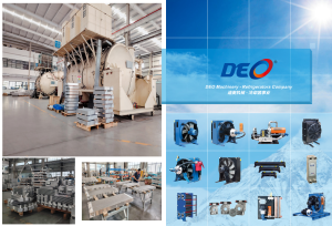
Heat exchanger and cooler range for lubrication and hydraulic cooling circuits. Image: DEO Machinery
The cooling decision follows the lubrication duty, not the other way round
The starting point is the lubrication circuit itself. The DK630 electric lubrication pump has a rated displacement of 630 cc/rev with motor rotation speed available at 950 rpm or 1450 rpm, and is built from QT500 ductile iron for machinery, heavy industry, steel, construction machinery and mining equipment. The PST180 bidirectional internal gear pump displaces 180 cc/rev at up to 1800 rpm within a −30°C to +100°C range, for engine lubrication, hydraulic power units and industrial cooling systems. The PSN100 trochoidal pump displaces 100 cc/rev at the same maximum speed and is intended for lubricating and cooling circuits and external drive independent conveying systems.
These pumps are expected to run continuously. The DK series is specified for 24/6 operation — 24 hours a day, six days a week — and the lubricating or hydraulic oil it handles may range from 12 to 20,000 cSt in kinematic viscosity at fluid temperatures from −40°C to 100°C. Continuous delivery at that duty means heat accumulates in the reservoir: friction heat from bearings and gears, plus the pressure losses of the circuit itself. Leave it there and the oil thins, oxidation accelerates, and seals, bushings and valves wear faster than their duty cycle assumes.
Three cooling architectures, three different site assumptions
Air cooling, water cooling and self-circulating air cooling all reject the same heat, but each makes a different assumption about what the plant can supply — and that assumption, not the headline rating, is usually what decides the match.
DFLEX8 wind cooler: assumes air is the cooling medium
The DFLEX8 is a wind cooler with a copper radiator — stainless steel available as a custom option — a comparative cooling capacity of 1.15 kW/°C or 0.91 kW/°C depending on configuration, a fan diameter of 630 mm and a 3-phase 380V fan motor. DEO lists it for hydraulic systems, lubricating systems, gearbox and reducer cooling, construction machinery, crude oil mining, coal mines, nuclear power plants and wind energy.
The design assumption is straightforward: there is no water circuit to install, treat, drain or protect from frost, and the oil is cooled by ambient air moved across a finned radiator. That makes the architecture a natural candidate where water is unavailable, expensive to route or seasonal — and a weaker candidate where the site already runs a cooling water network and needs tighter control of oil temperature.
DWBW-408-T oil/water cooler: assumes a clean water supply exists
The DWBW-408-T is a shell-and-tube finned heat exchanger. An expand-tube process bonds copper fins and heat-transfer tubes to raise heat exchange efficiency. The shell is carbon steel with an anti-rust coating, with a stainless steel shell available on request; heat-transfer tubes are high-purity copper and cooling fins are aluminum, with copper fins and 304 stainless steel listed as customization paths for corrosive duty.
Its ratings are explicit. Maximum working pressure is 16 bar on the oil side and 10 bar on the water side. Allowable oil medium temperature reaches 120°C, allowable cooling water temperature is 5–60°C, and applicable oil kinematic viscosity is 12–320 mm²/s, with heavy high-viscosity lubricant customizable. Single-unit heat exchange area runs from 1.3 m² to dozens of square metres across the wider DWBE-408 / DWBE-412 / DWBE-414 / DWBE-418 family. Oil connections are G1 and G1-1/2 standard thread flanges with SAE flanges optional, and the end cover is detachable so internal scale and sludge can be cleaned.
The water-cooled architecture assumes cooling water with low impurity content. Seawater and heavily polluted water are supported only through a customized anti-corrosion structure — not by the standard build.
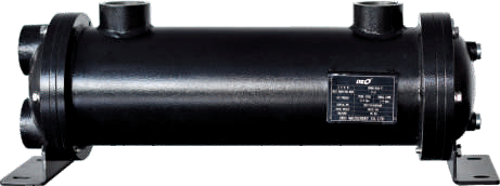
Fin-type oil/water cooler construction: carbon steel shell with anti-rust coating, high-purity copper heat-transfer tubes, detachable end cover. Image: DEO Machinery
DFLSL-10 self-circulating cooler: assumes an independent circulation loop
The DFLSL-10 is a self-circulating cooler that integrates radiator, circulating oil pump, cooling fan, filter and control accessories into one closed unit. Cooling capacity is 1.61 kW/°C or 1.84 kW/°C, oil pump flow is 100–125 L/min on VG46 oil with a 150–200 L/min variant, and consumed power is 5.5 kW or 7.5 kW. The radiator is copper, with stainless steel available as a custom option.
Within the DFLS series architecture, the built-in circulation pump extracts hot oil from the host tank or lubrication loop, delivers it to the radiator core where an axial fan forces air across the finned surface, and returns cooled oil to the reservoir — a circuit kept separate from the main hydraulic line so that pressure fluctuation in the host system does not disturb cooling performance. Series ratings include a 16 bar working pressure, an oil flow range of 6–200 L/min, standard oil inlet temperature up to 90°C with a customized maximum of 130°C, and compatibility with VG46 to VG320 oils. Optional elements change on-site behaviour: a temperature bypass valve opening between 45°C and 55°C shortens cold-start preheating, a pressure bypass valve absorbs instantaneous flow and pressure spikes, and temperature or pressure switches enable over-temperature and over-pressure alarms.
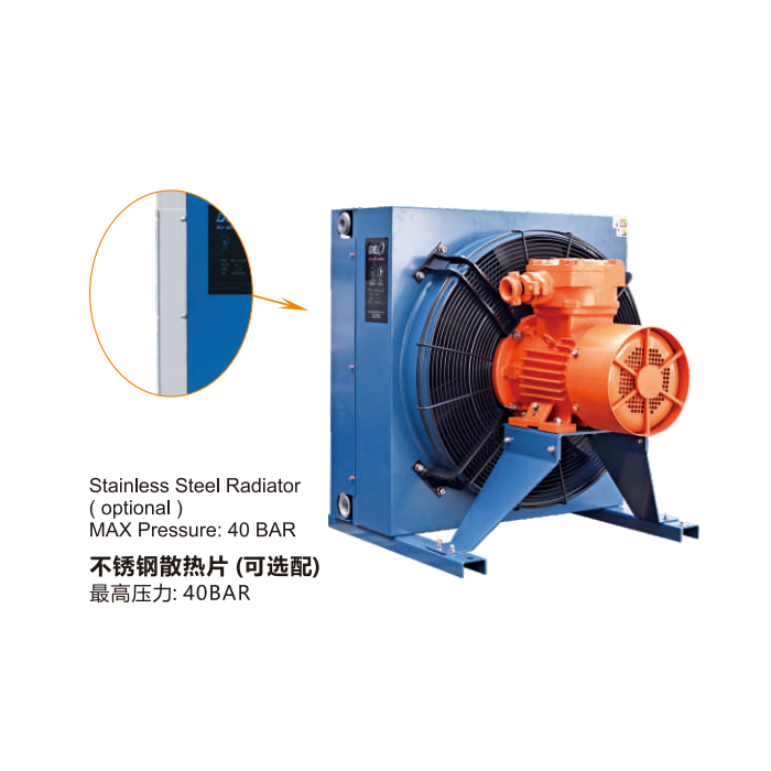
DFLEX series wind cooler: copper radiator and 630 mm fan diameter for air-side heat rejection in lubrication and hydraulic circuits. Image: DEO Machinery
The four criteria that decide the match
1. Cooling capacity and the temperature difference available to you
Cooling capacity in these ratings is expressed per degree Celsius (kW/°C), which means the figure describes heat rejection per degree of temperature difference between the oil and the cooling medium. Two consequences follow for buyers. First, the three units are not interchangeable at face value: the DFLSL-10 at 1.61/1.84 kW/°C sits above the DFLEX8 at 1.15/0.91 kW/°C. Second, and more important on site, capacity does not compensate for a narrow temperature difference. An air-cooled unit in a hot workshop and a water-cooled unit running on warm cooling water will behave very differently even on identical duty.
2. Fluid throughput
The cooler must pass the circulating flow without imposing excessive pressure loss. The DFLSL-10's 100–125 L/min rating on VG46 oil gives a useful reference point, while the wider DFLS series covers 6–200 L/min through different built-in circulation pump displacements. On the water-cooled side, the DWBW-408-T is specified for oils from 12 to 320 mm²/s with large-diameter oil ports intended to reduce flow resistance and pressure drop — relevant for high-viscosity lubrication oil, where a restrictive cooler can distort the pressure balance of the whole circuit. Where the lubrication pump delivers a large displacement per revolution, the cooler's rated flow and port size should be checked against actual circulation rather than against reservoir volume.
3. Radiator and wetted materials
Both the DFLSL-10 and the DFLEX8 use copper radiators with stainless steel available as a customization. The DWBW-408-T combines a carbon steel shell with anti-rust coating, high-purity copper heat-transfer tubes and aluminum fins, with stainless steel shells and nickel tube options for corrosive duty. The practical rule is to match materials to the fluid and the environment rather than to the purchase price — and to remember that a standard build does not automatically cover seawater or contaminated water, which requires the customized anti-corrosion structure.
4. Site constraints
- Water availability and quality. Oil/water cooling presupposes a supply at 5–60°C with low impurity content, plus a return or drain path. Where water is intermittent, air cooling removes an entire utility dependency.
- Ambient conditions. An air cooler's performance depends on the air it can move and how cool that air is. High-ambient or dust-laden areas change both fan selection and maintenance intervals.
- Power supply. The DFLEX8 fan motor is rated 3-phase 380V; the DFLSL-10 consumes 5.5 kW or 7.5 kW. Electrical supply and control wiring belong in the early comparison, not in the installation phase.
- Space and airflow. The DFLS series requires ventilation space around the radiator; blocking the air inlet or outlet defeats the unit. Installation can be floor- or bracket-mounted, and the mounting base requires shock-absorbing gaskets to limit vibration transmission.
- Maintenance access. The DWBW-408-T's detachable end cover exists because descaling and sludge removal is a routine task, not a fault event.
- Suction integrity. On self-circulating units, an oil suction line that is not airtight reduces circulation flow and cooling capacity sharply.
Side-by-side reference
| Criterion | DFLEX8 wind cooler | DWBW-408-T oil/water cooler | DFLSL-10 self-circulating cooler |
|---|---|---|---|
| Cooling medium | Ambient air, 630 mm fan | Cooling water, 5–60°C | Ambient air through closed self-circulation loop |
| Cooling capacity | 1.15 / 0.91 kW/°C | Rated by heat exchange area: 1.3 m² to dozens of m² | 1.61 / 1.84 kW/°C |
| Fluid throughput reference | Not stated as a flow rating | Oil viscosity 12–320 mm²/s, large-diameter oil ports | 100–125 L/min on VG46; 150–200 L/min variant; series 6–200 L/min |
| Radiator / wetted materials | Copper radiator, stainless steel custom option | Carbon steel shell (anti-rust coating), copper tubes, aluminum fins; stainless steel shell on request | Copper radiator, stainless steel custom option |
| Pressure / temperature envelope | Motor 3-phase 380V | 16 bar oil side, 10 bar water side, oil up to 120°C | 16 bar series rating, oil inlet up to 90°C standard (130°C custom) |
| Notable site requirement | Airflow space; no water circuit | Clean water; cleaning access for descaling | Ventilation space, airtight suction line, shock-absorbing mounting |
A six-step selection sequence
- Establish the continuous heat load and the target stable oil temperature for the circuit.
- Establish which cooling medium the site can guarantee — air, water, or both — and at what temperature.
- Establish circulating flow and oil viscosity, then confirm the cooler's rated flow, port size and pressure drop.
- Match wetted materials to the fluid and the cooling water chemistry.
- Verify site constraints: power, space, airflow, mounting, maintenance access.
- Decide whether temperature or pressure monitoring is required, and specify the switches and bypass valves accordingly.
Modern finned exchangers versus traditional tubular coolers
DEO positions the DWBW-408-T as a compact alternative to traditional tubular coolers: a fin-enhanced heat exchange surface with a small footprint relative to its heat dissipation capacity, low oil-side flow resistance, and a detachable end cover for regular descaling and sludge removal. The comparison is real, but it is also bounded. The same close fin spacing that raises heat transfer efficiency makes water-side cleanliness a maintenance discipline rather than an optional task — which is why DEO's own specification routes seawater and heavily polluted water to a customized anti-corrosion build instead of the standard unit. Buyers comparing a fin-and-tube exchanger against a traditional tubular cooler should compare them on water chemistry and cleaning frequency, not on heat exchange area alone.
Application fit by industry
- Wind energy. The DFLEX8 is listed for wind energy duty. The DWBW-408-T covers wind turbine gearbox lubrication cooling, with a seawater-capable version for coastal wind farms.
- Mining and coal. The DFLEX8 covers coal mines, crude oil mining and construction machinery. The DWBW-408-T covers mine reducer lubrication systems and heavy-duty excavator hydraulic stations, where its detachable end cover suits sites with poor water quality.
- Steel, forging and heavy machinery. The DFLSL-10 is listed for extruding machinery, forging and stamping equipment, shearing machines, gearboxes, large bearings, large-scale reduction boxes and smelting equipment — duties where stable oil temperature matters more than installation simplicity.
- Power and marine. The DFLSL-10 is listed for nuclear power plants; the DWBW-408-T covers marine gearboxes and marine hydraulic systems.
- Machine tools and hydraulic stations. The DWBW-408-T covers centralized hydraulic oil cooling for CNC machine tools, injection moulding machines and die-casting equipment.
Market signals behind the cooling decision
Cooling hardware sits inside a lubrication market that is being pulled toward automatic and electrically driven systems. A consolidated commercial market research summary places the global lubrication system market at USD 863.88 million in 2024 and reports that 67% of newly commissioned industrial machines in that year came equipped with automatic lubrication systems; the same source projects automatic lubrication systems reaching USD 1,470.88 million by 2032. A separate forecast attributes a 6.89% CAGR to the electric lubrication pump category toward USD 2.7 billion by 2032; that figure is source-reported and is best treated as directional rather than audited.
Two structural signals point the same way. A 2024 peer-reviewed study indexed in PubMed (PMID 38420457) describes intelligent lubricating devices that supply oil periodically to the feed systems of CNC machine tools. In the wider supply base, manufacturers including SKF, Graco and Ingersoll Rand each disclose electrically operated centralized lubrication pumps or lubrication gear pumps for machinery, turbines, gearboxes and production lines — a product category in which oil temperature control belongs to the same purchasing decision as the pump itself.
Classification and standards context matters to cross-border buyers as well. Industrial pumps and oil pumps sit under HS heading 8413.30 in the United States tariff schedule, and ASTM F2798-09(2023) defines requirements for sealless rotary positive displacement pumps with oil-through motors in ship lubricating oil service with SAE 20–50 oil. Neither reference decides cooler selection, but both illustrate how tightly pump duty, fluid grade and cooling are specified in regulated applications. For capacity context, United States sectoral output for pump and compressor manufacturing was reported at USD 23,000.913 million for 2021 — a sector-level figure that must not be read as lubrication pump revenue.
Where this framework stops
A decision framework is only useful if it states its own boundaries.
- No public cost benchmark. Price, minimum order quantity and lead time for these three coolers are not available in the data behind this analysis, so cost cannot be resolved here. Total cost of ownership has to be built from water utility cost, maintenance interval and downtime exposure instead.
- Air cooling is bounded by ambient conditions. When cooling air is hot, the temperature difference available to the radiator narrows; when airflow is blocked, the capacity rating becomes irrelevant.
- Water cooling is bounded by water chemistry and temperature. The DWBW-408-T accepts cooling water from 5–60°C and, in standard build, expects low impurity content.
- Self-circulating units add components. Circulation pump, bypass valves and switches are also additional maintenance items; filter replacement and suction airtightness become routine tasks rather than exceptions.
- All three assume clean oil. Particle contamination scratches gear surfaces and wears bushings regardless of how effectively the oil is cooled.
Future outlook
Two directions look likely to shape specification over the next planning cycle. The first is monitoring: temperature and pressure switches are already optional on the DFLS series to support over-temperature and over-pressure alarms, and the broader industry trend toward automatic and intelligent lubrication devices makes instrumentation a default rather than an add-on. The second is water-side pressure. As industrial water constraints tighten, the cost of maintaining a clean cooling water circuit becomes part of the cooler's evaluation rather than an operational footnote. Buyers specifying today can hedge on both fronts by choosing units whose materials allow an upgrade path — copper radiators with a stainless steel option, carbon steel shells with a stainless steel alternative — and by recording the oil temperatures the loop actually runs at, so the next specification starts from measured duty rather than assumed duty.
FAQ
What is the difference between a wind cooler and an oil/water cooler in a lubrication system?
A wind cooler rejects oil heat to ambient air through a finned radiator and a fan: the DFLEX8 uses a copper radiator with a 630 mm fan and a 3-phase 380V motor. An oil/water cooler transfers heat from the oil to a cooling water circuit: the DWBW-408-T is a shell-and-tube finned exchanger with a carbon steel shell, high-purity copper heat-transfer tubes and a 16 bar oil-side rating. The wind cooler requires no water supply; the water cooler requires cooling water at 5–60°C with low impurity content.
How do I choose between the DFLSL-10 self-circulating cooler and the DFLEX8 wind cooler?
Both are air-cooled; the difference is architecture and capacity. The DFLSL-10 is a closed self-circulating unit rated at 1.61/1.84 kW/°C with an internal circulation pump delivering 100–125 L/min on VG46 oil and consuming 5.5 kW or 7.5 kW. The DFLEX8 is a wind cooler rated at 1.15/0.91 kW/°C with a 630 mm fan, listed for hydraulic systems, lubricating systems, gearbox and reducer cooling, construction machinery, coal mines, crude oil mining, nuclear power and wind energy. The self-circulating unit is the fit when the cooling loop should operate independently of the host circuit; the wind cooler is the fit where a simpler air-side unit meets the duty.
What does a cooling capacity rating of 1.61/1.84 kW/°C mean in practice?
It expresses heat rejection per degree Celsius of temperature difference between the oil and the cooling medium. The actual heat the cooler removes grows as that difference grows, and shrinks when the difference narrows — for example, when ambient air is hot. For that reason the figure should be used as a comparison basis between units operating under the same site conditions, not as an absolute capacity that holds in every environment.
Can the DWBW-408-T be used with seawater or dirty cooling water?
Not in standard build. The standard unit uses a carbon steel shell with anti-rust coating, copper heat-transfer tubes and aluminum fins, and its specification calls for cooling water with low impurity content. Seawater and heavily polluted water are supported through a customized anti-corrosion structure, with stainless steel shells and nickel tubes listed as customization options. In all configurations the applicable oil kinematic viscosity is 12–320 mm²/s and allowable oil temperature is up to 120°C.
What operating conditions do lubrication pumps and their coolers share?
DEO's DK series lubrication pumps are specified for 24/6 continuous operation and handle lubricating or hydraulic oil with kinematic viscosity from 12 to 20,000 cSt at fluid temperatures from −40°C to 100°C. The DK630 electric lubrication pump displaces 630 cc/rev with motor speeds of 950 rpm or 1450 rpm and is built from QT500 ductile iron. All system components assume oil free of metal chips, sand and other solid impurities, since particle contamination scratches gear surfaces and accelerates bushing wear independently of cooling performance.
DEO publishes a downloadable product brochure covering its lubrication pumps and cooling equipment: DEO product brochure (PDF). Company information is available at www.cndeo.com.
¿Tiene preguntas o necesita más detalles?
Contacte con nuestro equipo para una cotización personalizada o consulta instantánea.
Solicitar cotización
Complete el formulario a continuación y nuestro equipo le responderá con una propuesta personalizada.
Chat directo de WhatsApp
¿Prefiere chatear en tiempo real? Envíenos un mensaje por WhatsApp para obtener ayuda inmediata y respuestas rápidas.
- Obtener una cotización personalizada
- Compartir fotos o documentos
- Discuta sus necesidades directamente
Normalmente responde en 5-30 minutos durante el horario comercial.