
BESS for EV Charging Hubs: Matching Storage to High-Duration Charging Loads
BESS for EV Charging Hubs: Matching Storage to High-Duration Charging Loads
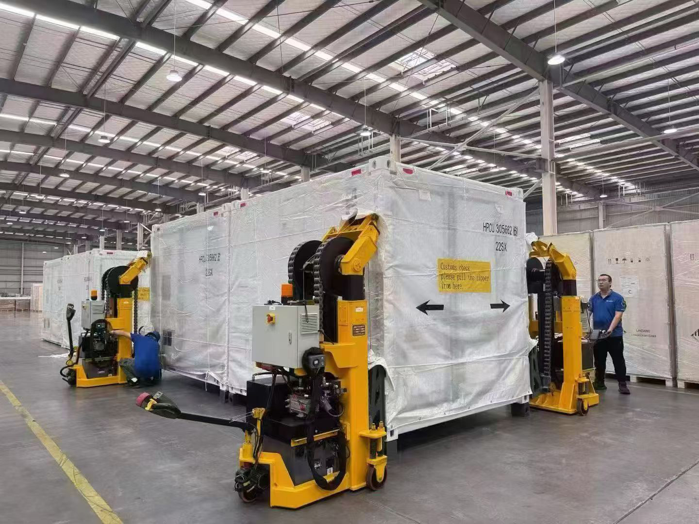
The sizing question at an EV charging hub is a subtraction problem. Chargers define a demand in kilowatts; the site transformer and its interconnection agreement define a limit; battery energy storage covers the difference. What determines whether that difference can be covered at all is not the number of chargers but the duration over which the peak must be held. High-power charging looks like a short event at a single connector and like a long event at the site level, because shift changes, fleet dwell windows and evening return peaks stack many vehicles into the same two to four hours.
Why the grid limit arrives before the charger limit
Charging hubs, logistics parks and fleet depots share a working condition that rarely appears in other storage applications: high short-duration charging demand, limited grid capacity and concentrated charging periods. The chargers themselves are usually the easy part of the project. The constraint sits upstream, at the service transformer and the connection the network operator is willing to grant.
Xupernova New Energy Technology Co., Ltd. (Xupernova), founded in 2015, is a manufacturer of energy storage and new energy solutions with a 700,000 m² production base, more than 500 employees, 150+ R&D engineers and 5GWh+ annual capacity, exporting roughly 90% of its output to Europe, North America, South America, the Middle East and Asia. Its charging-hub reference point is not theoretical: the company supplies both storage platforms and EV charging solutions, covering AC chargers, DC fast chargers and high-power charging systems.
The scale of the underlying market explains why this planning problem is spreading. Global new battery storage deployment reached 108 GW in 2025, and LFP chemistry accounted for approximately 90% of that deployment, according to the IEA's Global Energy Review 2026. In the United States alone, utility-scale battery storage capacity additions were projected at 19.6 GW in 2025, based on the U.S. Energy Information Administration's Preliminary Monthly Electric Generator Inventory. Storage is being deployed at industrial scale; the question for a charging-hub developer is how much of it belongs on their site, at what power rating and for how long.
Charging-load forecast: the input that decides storage duration
A charging-load forecast is not a count of connectors. It is a time-series estimate of coincident site demand, and it produces two different numbers that drive two different parts of the storage specification.
- Peak coincident demand (kW) sets the required discharge power of the storage system and the rating of the power conversion equipment.
- Energy under the peak (kWh) sets the energy capacity, and therefore the physical footprint, of the battery block.
Coincidence is the variable most often underestimated. Ten chargers of the same nameplate rating do not draw one tenth of their combined power when averaged across a day; they draw close to their full combined power when several vehicles arrive together. A hub with a morning departure wave and an evening return wave therefore has two peak windows per day, separated by a long low-load period — the shape that storage handles best.
| Forecast input | Why it changes the storage specification |
|---|---|
| Connector count and power rating | Defines the theoretical ceiling of site demand before any control is applied |
| Coincidence factor by hour | Converts connector nameplate into realistic simultaneous demand |
| Session energy and session duration | Separates short high-power events from sustained multi-hour load blocks |
| Arrival and departure distribution | Determines how many distinct peak windows the battery must serve per day |
| Fleet dwell schedule (depots) | Converts charging into a predictable overnight block with a known duration |
| Existing non-charging site load | Consumes transformer headroom and reduces the capacity available to chargers |
| Seasonal and future expansion | Prevents a specification that is compliant at commissioning and constrained two years later |
The distinction between short-duration and high-duration charging loads becomes concrete at this point. A public fast-charging site may see a 20-minute peak; a logistics park or fleet depot typically sees a peak that persists for hours while vehicles are plugged in and drivers are off shift. The second case is the harder one, because both the power requirement and the energy requirement grow at the same time.
Transformer-capacity assessment: how much headroom actually exists
The transformer assessment answers one question: how much import capacity can the charging load use without exceeding the site's agreed limit? The assessment normally covers the existing service transformer rating, the firm import limit granted by the network operator, the measured coincident demand of the existing facility, and the residual capacity that remains for charging.
Two measurement devices make this assessment usable in real time rather than on paper. A smart meter and current transformers (CTs) at the point of common coupling give the energy management system a continuous reading of site import, which is the signal that dynamic power allocation acts on. Around them sits the conventional distribution equipment — transformer, switchgear and power distribution equipment — plus the charging management system that communicates with the chargers themselves.
The boundary condition that matters: storage defers a capacity upgrade; it does not remove the need for one. A BESS reduces peak import, so a hub can add chargers without immediately paying for a larger transformer and service. But if the total daily charging energy required by the depot exceeds what the existing connection can deliver over 24 hours, no amount of peak shaving closes the gap — the upgrade returns as a requirement, only later.
Matching storage rating to charging duration
Energy capacity divided by power rating gives the discharge duration of a storage block, and that single ratio explains most of the difference between a charging-hub specification and a conventional peak-shaving specification. The published ratings of Xupernova's storage platforms illustrate the arithmetic at the 0.5P configuration.
| Model | Type | Rated power / energy | Energy ÷ power at the stated 0.5P rating |
|---|---|---|---|
| XA-C0261-L1 | Liquid-cooled all-in-one ESS cabinet | 125 kW / 261.25 kWh | Approximately 2 hours |
| XA-X1044-L1 | 10-ft liquid-cooled all-in-one ESS container | 500 kW / 1044 kWh | Approximately 2 hours |
| XA-X2170-L2 | 20-ft liquid-cooled all-in-one ESS container | 1125 kW / 2170.3 kWh | Approximately 2 hours |
| XA-V5015-L1 | 20-ft liquid-cooled battery container | 5.015 MWh, 0.5P/1P/2P | Ratio set by the selected P configuration |
| XA-H0261-L1 | Liquid-cooled solar-plus-storage cabinet | 261 kWh, 0.5P/1P/2P | Ratio set by the selected P configuration |
| XA-H0064-A1 | Air-cooled solar-plus-storage cabinet | 25–50 kW / 64.54 kWh | Small-scale, single-point application |
Each model in the container and cabinet families is offered in 0.5P, 1P and 2P configurations. In practical terms this means the same energy block can be ordered as a longer, gentler discharge or a shorter, more powerful one. A depot that must hold a 500 kW charging peak for two hours needs the energy block rated at 0.5P; a hub that must shave a single sharp 20-minute window may be better served by a smaller energy block rated at higher power. The usable duration in service will be shorter than the arithmetic above, because depth of discharge, ambient conditions and end-of-life capacity all reduce delivered energy — a specification should be checked against the load profile at the end of the warranty period, not only at commissioning.
All listed platforms share the same cell sourcing basis: Grade A LFP lithium-ion cells from BloombergNEF Tier 1 energy-storage cell manufacturers, with optional semi-solid-state, solid-state and sodium-ion technologies subject to project requirements, technical validation and availability. The operating scope for the platform family is -30°C to 55°C, which matters at charging sites because equipment is frequently installed outdoors under a canopy rather than inside a conditioned room.
Dynamic power allocation: what the EMS does minute to minute
Dynamic power allocation is the mechanism that keeps a hub inside its connection limit without switching chargers off entirely. It works by continuously measuring site import and deciding, in real time, how much power each element of the site may draw or supply.
The operating mode at a storage-supported charging hub is automatic coordination of grid power, solar PV, battery storage and EV charging loads through the energy management system. In practice this combines three control behaviours already used in commercial and industrial storage: scheduled charging and discharging, load-following control, and demand-limit control. When import approaches the limit, the EMS discharges the battery or reduces charger output in a defined order; when import falls below the limit, it releases charger power or recharges the battery.
Where solar is present, coordination extends to photovoltaic generation and consumption. PV generation assessment and export limitation requirements are part of the design, and PV–battery control is coordinated so that solar energy is stored or consumed on site rather than exported at an unfavourable moment. The XA-H0261-L1 solar-plus-storage cabinet and the smaller XA-H0064-A1 air-cooled cabinet are the two solar-integrated platforms in the range, sized for commercial and small-scale commercial sites respectively.
Backup is a separate function and requires separate hardware. Islanded operation of selected loads requires a grid-forming PCS together with an STS or EPS transfer function; grid-connected operation is normal, and the transfer to islanded backup happens automatically during a grid outage when that configuration is present. At a fleet depot this is typically used to keep a defined set of loads — dispatch office, lighting, a limited number of charge points — energised rather than the whole site.
Grid-connection approval: the evidence a network operator reviews
Grid-connection approval is a documentary process as much as an electrical one. The network operator assesses how the storage and charging equipment behaves on the network — protection settings, anti-islanding behaviour, power quality and grid-support response — and the evidence is provided through product-level compliance documents that must match the model being installed and the market being connected.
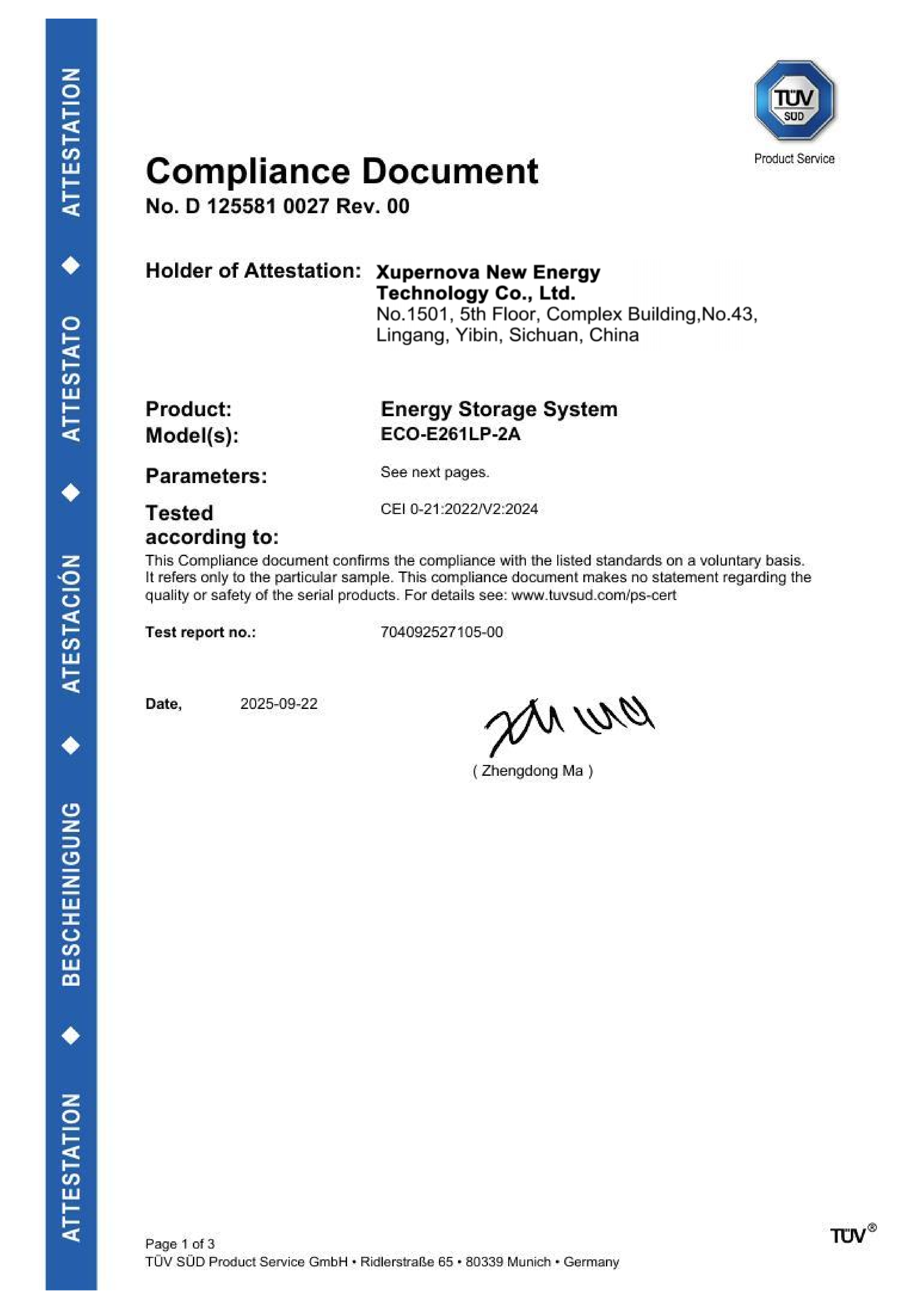
Xupernova's compliance set for its 125 kW / 261.248 kWh, IP55 energy storage system illustrates the kind of documentation involved:
- CEI 0-21:2022/V2:2024 compliance document (certificate no. D 125581 0027 Rev. 00) and CEI 0-16:2022/V3:2024 compliance document (certificate no. D 125581 0028 Rev. 00), issued by TÜV SÜD Product Service GmbH for the Italian market, covering energy storage system model ECO-E261LP-2A.
- EMC attestation of conformity (certificate no. E8A 125581 0023 Rev. 00) against EN IEC 61000-6-4:2019 and EN IEC 61000-6-2:2019 for the EU market.
- LVD attestation of conformity (certificate no. N8A 125581 0024 Rev. 00) against EN 62477-1:2012/A12:2021.
- IEC 63056:2020 product certificate (certificate no. B 125581 0022 Rev. 01) for the rechargeable lithium-ion battery system, rated DC 832 V, 314 Ah.
Deployment history shows how market-specific evidence is applied in practice. A commercial facility and solar EPC contractor project used 500 kW / 1.044 MWh units with up to 1 MW of PV input across 32 units. A renewable energy project developer installation used 2 MW / 4.176 MWh across seven 10-ft container units with G99 grid-code compatibility referenced in the project record. An industrial manufacturing deployment of 1 MW / 2.09 MWh across 20 units referenced compatibility with German grid requirements, and a supermarket and retail facility operator rollout of 125 kW / 261.248 kWh cabinets across 50 units referenced compatibility with Italian grid requirements.
Two practical cautions follow. First, grid codes differ by market and by connection voltage, and a certificate issued for one market does not transfer to another. Second, buyers importing equipment into the United States should note that BESS fully encased in housing is classified under US HTS 8507.60.00.90, a detail that affects landed-cost calculation and customs documentation.
Fire-safety compliance where vehicles and people are present
Fire and thermal runaway are recognised risks in battery energy storage, triggered by abnormal cell temperature, internal short circuit or thermal-propagation conditions during operation. The mitigation set used in Xupernova's storage platforms combines multi-level temperature monitoring, BMS protection, liquid cooling, automatic alarm and emergency shutdown with multi-layer fire-suppression hardware: LFP cells, smoke and temperature detection, PACK-level and cluster-level aerosol fire suppression, and a water fire-fighting interface. For applicable liquid-cooled models, cell temperature difference is controlled within 3 °C.
At a charging hub these measures interact with the site layout. Storage cabinets and containers sit near parked vehicles, frequently under canopies, and the site's alarm and emergency response arrangements must be coordinated with the storage system's own detection. Fire safety compliance is one of the five design requirements a competent integrator works through alongside the charging-load forecast, transformer-capacity assessment, dynamic power allocation and grid-connection approval.
The limits of product-level evidence should be stated plainly. A compliant product certificate is not a substitute for a site-level fire-safety review, and requirements differ by jurisdiction, by installation distance from occupied buildings and by the authority having jurisdiction. LFP's share of approximately 90% of 2025 global deployments reflects a chemistry preference, not a waiver of those local requirements.
Where the configuration fits: forecourts, logistics parks, fleet depots
The same design method produces different hardware answers depending on the site type, because the shape of the charging load differs.
| Site type | Dominant load shape | Storage role | Platform fit |
|---|---|---|---|
| Forecourt or roadside charging station | Short, high-power public sessions | Peak shaving, demand-limit control | XA-C0261-L1 (125 kW / 261.25 kWh cabinet) |
| Charging hub with solar canopy | Daytime PV generation, evening charging peak | PV self-consumption, peak shaving, optional backup | XA-H0261-L1 (261 kWh solar-plus-storage cabinet) |
| Small commercial site with a few charge points | Low simultaneous demand | Solar self-consumption, light peak shaving | XA-H0064-A1 (25–50 kW / 64.54 kWh air-cooled cabinet) |
| Logistics park with DC fast charging | Multi-hour blocks during shift windows | Capacity support, demand-limit control, modular expansion | XA-X1044-L1 (500 kW / 1044 kWh 10-ft container) |
| Fleet depot with high-power charging | Sustained overnight and shift-change blocks | Peak shaving, load shifting, islanded backup of selected loads | XA-X2170-L2 (1125 kW / 2170.3 kWh 20-ft container) |
| Large depot or grid-side support | Long, high-energy blocks | Energy shifting, grid capacity support | XA-V5015-L1 (5.015 MWh container) |
The operational evidence behind these configurations comes from adjacent applications that share the same control logic. A commercial and industrial park operator project of 1 MW / 2.088 MWh across 12 units combined a solar-plus-storage microgrid with emergency backup and diesel generator optimisation, using integrated STS, grid-connected and off-grid switching, photovoltaic and diesel generator interfaces, and centralised energy management. A similar control pattern — utility power, on-site generation, storage and a variable load, coordinated by one controller — is what a charging hub requires.
Comparison with traditional solutions
| Approach | What it provides | Typical constraint | Where it fits |
|---|---|---|---|
| Interconnection and transformer upgrade only | Permanent increase in firm import capacity; no daily operating limit | Capital cost, switchgear and transformer space, and a permitting and construction timeline set by the network operator | Sites whose sustained daily energy demand already exceeds the existing connection |
| Diesel generator support | Added capacity and backup with a familiar service model | Fuel logistics, emissions, noise, operating cost, and permit conditions that limit run hours in some jurisdictions | Remote or temporary sites where an electrical upgrade is impractical |
| BESS with dynamic power allocation | Caps site import, shifts charging energy across the day, absorbs on-site solar, and can serve selected loads during outages when configured with grid-forming PCS and STS/EPS | Cannot create energy; usable duration is bounded by the energy block; requires load forecast, protection coordination, grid-connection approval and fire-safety review | Hubs and depots where the peak, not the daily total, is the binding constraint |
| Charger-side load management only | Keeps site demand below the limit by reducing charger output | Adds no energy and no capacity; slows charging and lengthens queues | Sites with occasional coincidence and no queue pressure |
The honest limitation of the storage approach is arithmetic rather than technical. A battery shifts energy within a day; it does not add energy to the site's daily budget. Where a fleet must charge a fixed number of vehicles every night and the daily energy required exceeds what the connection can deliver, storage alone fails and an upgrade becomes unavoidable. Conversely, a site whose peaks are rare and whose daily energy fits comfortably inside the connection limit may not justify storage at all — charger-side load management is cheaper, though it costs charging speed. A useful cost reference exists on the utility-scale side: all-in project CAPEX for long-duration (4h+) utility-scale projects reached $125/kWh in late 2025 according to Ember, but that figure describes grid-scale four-hour projects and should not be transferred directly to a hub-scale cabinet or container deployment.
Market context should also be read carefully. The global BESS market was estimated at $50.81 billion in 2025 by MarketsandMarkets, while other research providers report substantially lower valuations for the same year because they count only part of the value chain. The definition of what is being counted, not only the underlying demand, drives those differences.
Procurement and delivery considerations for hub projects
Charging-hub storage is frequently a fast-track purchase, which makes delivery terms part of the technical specification. Xupernova provides OEM and ODM production services for battery energy storage systems, and the documented customization scope covers system power and energy capacity, charge and discharge duration, AC and DC voltage, battery chemistry and cell supplier, PCS, BMS and plant-level EMS, photovoltaic input and solar-plus-storage configuration, on-grid and off-grid operation, STS and EPS backup function, cooling system, fire protection system, enclosure size, colour and branding, IP rating and corrosion protection, grid code, communication protocols, and transformer and switchgear configuration.
On the commercial side, monthly capacity reaches up to 500 MWh, with lead times of 25–35 days for standard BESS and 35–60 days for customised projects, and a minimum order quantity of one unit. Delivery can be arranged EXW, FOB, CIF or DAP/DDP. Every unit passes 100% FAT before shipment, with electrical safety testing, functional testing, ageing testing, and third-party inspection available; site acceptance testing is also offered. The standard payment term is 30% deposit with 70% before shipment after FAT. After-sales coverage includes 24/7 remote support, commissioning, training, diagnostics, spare parts and optional on-site service.
Future outlook
Three shifts are visible in the data. First, storage deployment is scaling fast enough that interconnection capacity, not battery availability, is becoming the limiting factor for new charging infrastructure. Second, LFP chemistry now dominates deployment, which stabilises the specification basis for high-cycle daily duty and simplifies the safety case for planners. Third, project economics continue to improve at the utility-scale end of the market, which changes the comparison at hub scale indirectly: a deferral of transformer capacity that once looked marginal becomes easier to justify as storage costs fall.
The planning consequence is procedural rather than technological. Charging hubs are moving from a charger-count design model to a capacity-planning model in which the charging-load forecast, transformer assessment and storage duration are decided together, and in which grid-connection approval and fire-safety compliance are scheduled as design tasks rather than administrative steps after equipment selection.
FAQ
How much battery storage capacity does an EV charging hub need?
Sizing follows two numbers. The required power rating equals the shortfall between the site's coincident peak charging demand and the import capacity available to chargers; the required energy capacity equals that shortfall multiplied by the duration the peak must be sustained. The available platforms differ mainly in that ratio: the XA-C0261-L1 cabinet provides 125 kW / 261.25 kWh, the XA-X1044-L1 container 500 kW / 1044 kWh, and the XA-X2170-L2 container 1125 kW / 2170.3 kWh, and the container and cabinet families are offered in 0.5P, 1P and 2P configurations so power and duration can be traded within a fixed energy block. Final sizing requires a charging-load forecast and a transformer-capacity assessment, because the binding constraint is often the site's existing coincident load rather than the chargers.
Can a battery energy storage system remove the need for a grid upgrade at a charging site?
It can defer one, not substitute for one indefinitely. Storage reduces peak import, so a hub can add charging capacity without immediately paying for a larger service and transformer, but total daily energy demand still has to fit within what the connection can deliver over a full day. Where a depot's nightly charging energy exceeds that figure, no amount of peak shaving is sufficient and an interconnection upgrade remains necessary. Storage also does not add energy to the site; it moves consumption within the day, so the decision rule is whether the binding constraint is peak power or daily energy.
How does an EMS coordinate grid power, solar PV, battery storage and EV charging loads?
An energy management system uses metering at the point of common coupling — typically a smart meter with current transformers — to read site import continuously, then adjusts battery charge and discharge, photovoltaic utilisation and charger allocation against that reading. Three control behaviours are combined: scheduled charging and discharging, load-following control, and demand-limit control. Where PV is installed, photovoltaic generation assessment and export limitation requirements are incorporated and PV–battery control is coordinated so that solar energy is consumed or stored on site. The supporting equipment set normally includes the chargers, a charging management system, the PV system where applicable, the storage system, transformer, switchgear, power distribution equipment and communication cables.
What fire-safety measures apply to battery storage at a charging hub?
Thermal runaway and fire are recognised risks in battery energy storage, triggered by abnormal cell temperature, internal short circuit or thermal-propagation conditions. Mitigation combines multi-level temperature monitoring, BMS protection, liquid cooling, automatic alarm and emergency shutdown with multi-layer fire-suppression hardware: LFP cells, smoke and temperature detection, PACK-level and cluster-level aerosol fire suppression, and a water fire-fighting interface. In applicable liquid-cooled models, cell temperature difference is controlled within 3 °C. Site-level requirements vary by jurisdiction and by distance from occupied buildings, and product certification does not replace a site-specific fire-safety review; fire-safety compliance is one of the defined design requirements for charging-hub storage alongside the load forecast, transformer assessment, dynamic power allocation and grid-connection approval.
Which compliance documents matter for grid-connection approval of storage at a charging site?
Approval depends on model-specific evidence that matches both the equipment and the market. Xupernova's compliance set for its 125 kW / 261.248 kWh, IP55 energy storage system includes CEI 0-21:2022/V2:2024 and CEI 0-16:2022/V3:2024 compliance documents issued by TÜV SÜD Product Service GmbH for the Italian market, an EMC attestation of conformity against EN IEC 61000-6-4:2019 and EN IEC 61000-6-2:2019, an LVD attestation of conformity against EN 62477-1:2012/A12:2021, and an IEC 63056:2020 product certificate for the rechargeable lithium-ion battery system rated DC 832 V, 314 Ah. Project records also reference G99 grid-code compatibility in a UK market installation and German grid requirements in a German installation. Because grid codes vary by market and connection voltage, buyers should verify that the certificate scope names the model being purchased rather than assuming transferability between markets.
Xupernova's energy storage platforms, specifications and configuration options are documented in its product catalogue, available for download: Xupernova Energy Storage Product Catalog.