
3D Scanners for Deviation Inspection: Key Specs and Limits
Dimensional deviations are rarely visible before assembly, and they are even harder to explain when a conventional gauge only captures a few points. Deviation inspection with a 3D scanner changes this by turning an entire part surface into a digital dataset that can be compared directly with a CAD model. SHINING 3D Tech Co., Ltd., founded in 2004 and headquartered in Hangzhou, develops high-precision 3D scanning hardware and software used in many of these quality-control workflows.
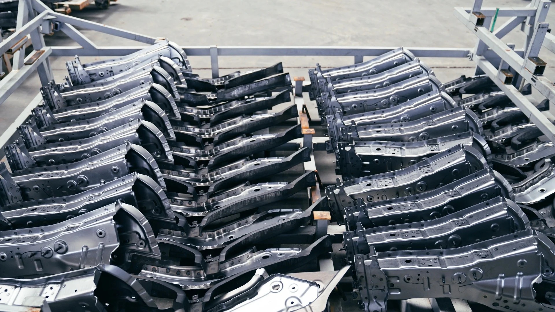
Automotive sheet metal components are common candidates for full-field 3D deviation analysis.
What Deviation Inspection Actually Requires
Deviation inspection compares the physical geometry of a manufactured part with its intended nominal geometry. In a 3D inspection workflow, the physical part is scanned, the resulting point cloud or mesh is aligned to the reference CAD model, and software calculates the distance between the measured surface and the nominal surface. The output is typically a color map that shows where the part is inside, outside, or on tolerance.
This approach is different from key-point inspection. Calipers, height gauges, and hard fixtures are efficient when a quality engineer knows exactly which dimensions will fail. But most complex parts have curved surfaces, stamping radii, weld zones, or freeform panels where a deviation can hide between two measured points. A 3D scanner captures that missing information without physical contact.
The same principle applies to a wide range of quality-control use cases: first article inspection, sheet metal inspection, stamping die inspection, mold wear inspection, MRO inspection, and production monitoring. In automotive, scanners are used on body panels, stamping parts, engine and powertrain components, and NEV battery housings. In mold manufacturing, scanning is used to quantify wear and deformation on tooling. In heavy industry, large structural components are checked for dimensional conformity before machining or assembly.
How 3D Scanning Technology Produces Deviation Data
Most industrial 3D scanners use one of two optical measurement approaches. Laser-line scanners project laser lines onto a surface and calculate depth from the deformation of those lines. Structured-light scanners project fringe patterns and use one or more cameras to reconstruct surface coordinates. Both methods generate dense point data that can be edited, aligned, and compared to a CAD reference.
A practical quality-control workflow has several stages:
- 3D data acquisition with a handheld, fixed, or automated scanner.
- Processing and alignment of the point cloud or mesh to the CAD model.
- CAD comparison using deviation color maps, section analysis, and GD&T evaluation.
- Report generation for traceability, supplier quality, and corrective action.
When a deviation is found, it can be interpreted by an engineer rather than baked into a single pass-fail decision. That makes 3D scanning especially useful during process development, tooling validation, and root-cause analysis.
Scanner Form Factor Matters for Deviation Detection
One scanner cannot optimize every deviation-inspection situation. Part size, tolerance, access to the part, and production volume all influence the right hardware. The table below compares the main industrial scanner families used for deviation inspection.
| System | Typical role | Key published specification |
|---|---|---|
| FreeScan Combo Series | Handheld hybrid-source scanning for shopfloor quality control. | Accuracy 0.02 mm; volumetric accuracy 0.02 + 0.033 mm/m; multiple scan modes including 50 laser lines, 26 laser lines, 7 parallel lines, and single-line deep-pocket scanning. |
| FreeScan Trak Nova Series | Wireless dynamic tracking for medium-to-large parts and marker-free scanning. | Accuracy 0.02 mm; scan speed up to 7,600,000 points/s; integrated Video Photogrammetry with volumetric accuracy of 0.046 mm + 0.012 mm/m in extension volume. |
| OptimScan Q12/Q9 and Q12/Q9 HD | Fixed high-precision inspection for small components, complex geometries, and highly detailed surfaces. | OptimScan Q12/Q9 provides up to 0.005 mm accuracy in small-range mode; Q12/Q9 HD provides up to 0.004 mm accuracy in small-range mode with four high-resolution cameras. |
| AutoScan Inspec2 | Desktop automated inspection for small precision parts such as electronic components. | Accuracy up to 0.01 mm; two 5MP industrial cameras; AI-assisted supplementary scanning; one-click fully automated operation. |
Accuracy and Traceability Are Separate Questions
A scanner may produce detailed visual data, but deviation inspection for engineering release requires metrological confidence. For that reason, industrial buyers should ask about acceptance standards and the laboratory used for verification.
Metrology-grade 3D scanners from SHINING 3D are tested in an ISO/IEC 17025 accredited Accuracy Laboratory. The FreeScan Combo Series is certified in accordance with VDI/VDE 2634 Part 3 and ISO 10360 standards. The FreeScan Trak Nova Series is compliant with VDI/VDE 2634 Part 3 and ISO 10360 and is also tested in an ISO/IEC 17025 accredited accuracy lab. The OptimScan Q12/Q9 Series is tested according to VDI/VDE 2634 and ISO 10360 in an ISO/IEC 17025 accredited laboratory. Those standards matter because they verify optical measurement systems rather than relying only on a manufacturer marketing claim.
The phrase volumetric accuracy is also important when scanning large parts. A scanner can have a strong single-frame accuracy, but errors can accumulate as the operator scans across a large object. Volumetric accuracy expresses the expected error over the full measurement volume. For the FreeScan Combo Series, volumetric accuracy is 0.02 + 0.033 mm/m. For the FreeScan Trak Nova Series, Video Photogrammetry helps maintain volumetric accuracy at 0.046 mm + 0.012 mm/m in extended volumes. This distinction becomes important in sheet metal panels, vehicle bodies, large castings, ship hulls, and construction machinery components, where the deviation can be small locally but the part is too large for a CMM work envelope.
The Practical Advantage Over Hard Fixtures and Checking Tools
Traditional checking fixtures are still used in many stamping and sheet metal plants. They are reliable for a defined product, but they are also part-specific. In one documented automotive stamping case, a typical fixture took 1.5 to 2 months to design and build. The manufacturer replaced that waiting period with a high-precision 3D scanning workflow and reduced project time by at least one-third. A scanner also does not need to be rebuilt when the part design changes.
The same case showed another benefit: fixture inspection often touches the part with probes, which is risky for thin stamped parts. 3D scanning is non-contact, so it captures geometry without pressure and without deforming the workpiece. This is a meaningful advantage for sheet metal parts and other flexible components.
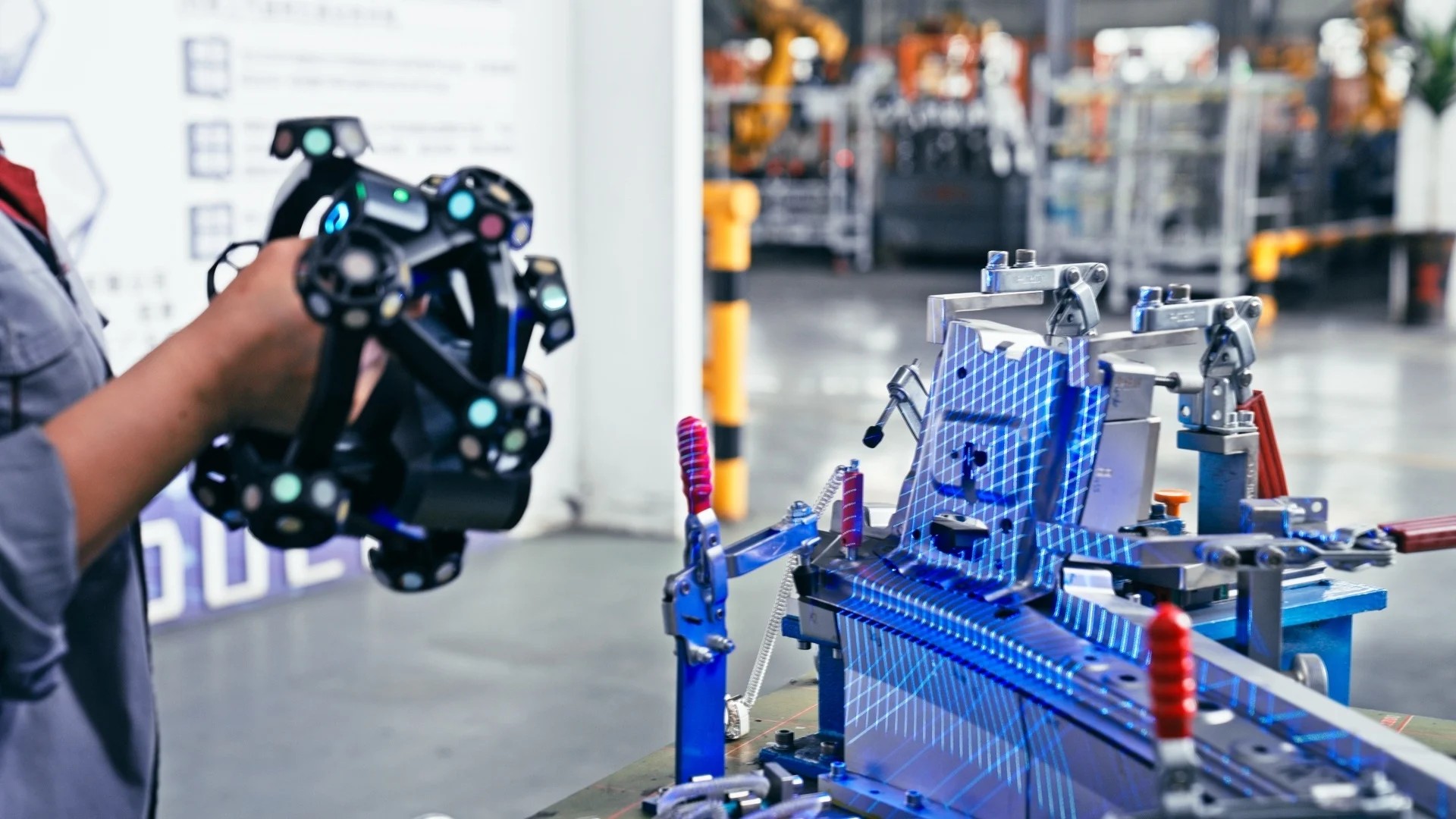
A dynamic tracking scanner can inspect sheet metal parts directly beside the production area.
Compared with CMMs, the main advantage of 3D scanning is not always accuracy. A CMM remains a high-precision reference for critical geometric features. But a CMM usually requires a controlled laboratory, programming time, and a fixed measurement envelope. In an aerospace PMA component inspection case, a CMM required two to three days to set up a program for a single part. The same data was captured in less than half a day using a FreeScan Combo+, without detailed programming or complex fixtures. This type of time saving changes how often a part can be checked.
Deviation Data Without Marker Preparation
One of the hidden costs in industrial 3D scanning is preparation. Many conventional scanners require reflective markers on the part before scanning. For large parts, applying and removing those markers can take longer than the actual scan.
Dynamic tracking systems address this in a different way. The FreeScan Trak Nova Series allows the scanning system to track the scanner position without reference markers for most parts. The system also handles a large field of view of up to 2600 mm by 2200 mm, making it useful for sheet metal stamping, vehicle body sections, and large structural workpieces. Video Photogrammetry provides additional global accuracy control when the part extends beyond the normal tracking volume.
For smaller workpieces, the FreeScan Combo Series uses infrared VCSEL light in addition to blue laser, allowing feature-rich parts to be scanned without applying markers. This makes it simpler to move between inspection and reverse engineering tasks on the shop floor.
Automated Inline and Desktop Inspection for Repetitive Deviations
When the same part is produced in high volume, operator consistency becomes a concern. Automated inspection reduces operator influence and allows measurement data to be generated in a predictable cycle. SHINING 3D automation solutions such as the RobotScan Series combine a scanner with an industrial robot, a turntable, and inspection software. The RobotScan configuration can include different scanner technologies depending on part material and geometry.
For very small precision parts, the AutoScan Inspec2 provides a desktop alternative. It has a maximum scan range of 140 x 90 x 80 mm, an accuracy of up to 0.01 mm, and supports path storage so that repeated parts can be scanned in batch mode with one-click operation. This makes automated deviation checks possible for small electronic housings, connectors, and mechanical components without creating a full robotic cell.
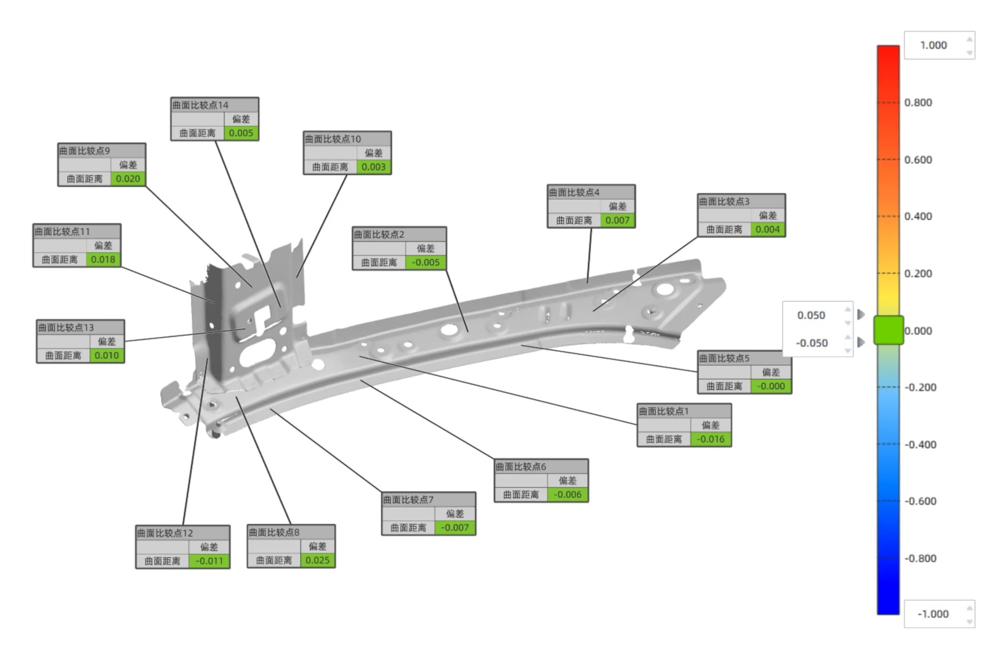
Color maps make out-of-tolerance areas easier to communicate across engineering and quality teams.
Industry Trends Support Full-Field Inspection
The wider manufacturing market is already moving in this direction. The global 3D scanning market was estimated at USD 4.28 billion in 2024 by Grand View Research, with quality control and inspection contributing to demand. Precedence Research identified quality control and inspection as the largest application segment of the 3D scanner market in 2024. The global 3D metrology market, which includes scanners, was estimated by MarketsandMarkets at USD 11.13 billion in the same year. North America held the largest regional revenue share in 2024, while Asia Pacific is projected to be the fastest-growing region through 2029.
Within manufacturing, inline automation is becoming more visible. Market analysis from Mordor Intelligence points to a shift from offline checking to inline 3D automated inspection in the electronics sector to improve first-pass yield. For deviation inspection, that means manufacturers are asking scanners not only to find a defect but to feed the measurement back into process control.
Selection Constraints Buyers Should Not Ignore
Although 3D scanning is versatile, it is not a universal replacement for every measurement tool. There are several constraints that should influence a purchasing decision:
- Required tolerance: For parts with strict GD&T requirements, choose a scanner with documented accuracy in the relevant range and traceable acceptance testing.
- Part size and access: Large parts need large-field handheld or dynamic tracking systems; small internal features may need high-resolution fixed scanners or a probe method.
- Surface reflectivity: Blue laser systems handle dark and reflective surfaces better than many older systems, but highly glossy or translucent parts may still require surface spraying or careful lighting.
- Workflow integration: Deviation data is only useful when the software can align to CAD, run GD&T, and generate reports. Compatibility with tools such as PolyWorks, Geomagic Control X, or SHINING3D Inspect is a practical requirement.
- Environment: Shopfloor scanning should tolerate temperature variation, humidity, dust, and vibration. Portable wireless scanners are often easier to use next to a production line than laboratory-bound fixed systems.
Another limit is technical. A 3D scanner measures visible surface geometry. If a defect or deviation is inside a deep internal channel or hidden cavity, optical scanners may not reach it without additional hardware. In those cases, a tactile probe or CMM may still be necessary. Similarly, a scanner does not make a quality decision by itself. A quality engineer must still define the tolerance frame, alignment strategy, and acceptable rejection criteria.
Outlook for Shopfloor Verification
Deviation inspection will keep moving closer to the point of manufacture. Wireless handheld scanners already allow inspection directly on the shop floor or at the side of a machine. Dynamic tracking scanners eliminate markers and reduce preparation time. Fixed high-precision systems bring micrometer-level data to small-part quality control. In the near future, more of these systems will be connected to automated cells, producing deviation reports that can be used not only for acceptance but also for tool maintenance and process adjustment.
For buyers, the most important change is not the scanner hardware itself. It is the shift from asking a few questions about a part to asking every surface of the part. That shift makes 3D scanners a practical intermediary between hand tools and CMMs, especially when the goal is finding deviations before they become assembly problems.
Readers who want additional product and company background can download the SHINING 3D corporate introduction brochure at the link below.
SHINING 3D 3D Digitizing Introduction
FAQ
What is the most important specification for a 3D scanner used in deviation inspection?
There is no single spec. Accuracy, volumetric accuracy, point density, scan speed, and field of view all play a role. For small parts with tight tolerances, fixed structured-light scanners such as the OptimScan Q12/Q9 HD are often chosen. For large sheet metal or welded fabrications, portable scanners or dynamic tracking systems are preferred because they cover more area more quickly.
Can a 3D scanner replace CMM for deviation inspection?
It can replace a CMM in many inspection applications, especially complex freeform surfaces and large parts that cannot fit in a CMM envelope. A CMM remains a strong reference for critical geometric features and for measurements that need tactile probing in controlled lab conditions. Many quality departments use both: 3D scanning for full-field shopfloor data and CMMs for validating specific features.
Are SHINING 3D scanners traceable to international standards?
Metrology-grade models are tested in the SHINING 3D Accuracy Laboratory, which operates in accordance with ISO/IEC 17025. The FreeScan Combo Series, FreeScan Trak Nova Series, and OptimScan Q12/Q9 Series are tested according to VDI/VDE 2634 and ISO 10360 standards, depending on the model. The AutoScan Inspec2 carries certifications including CE, FCC, ROHS, WEEE, and KC.
Does wireless operation affect measurement accuracy?
No. Wireless connectivity is used for data transmission. It does not change the optical measurement or the calibration of the scanner. Systems such as FreeScan Trak Nova and FreeScan Combo+ Wireless maintain the same accuracy in wired and wireless modes.
What is the difference between accuracy and volumetric accuracy?
Accuracy describes how close a single measured point or feature is to its true value. Volumetric accuracy describes measurement error across a large scanning volume. For a 2 m part, small single-shot errors can accumulate over distance. Volumetric accuracy formulas, such as 0.02 + 0.033 mm/m, communicate the expected error over the full object size.
¿Tiene preguntas o necesita más detalles?
Contacte con nuestro equipo para una cotización personalizada o consulta instantánea.
Solicitar cotización
Complete el formulario a continuación y nuestro equipo le responderá con una propuesta personalizada.
Chat directo de WhatsApp
¿Prefiere chatear en tiempo real? Envíenos un mensaje por WhatsApp para obtener ayuda inmediata y respuestas rápidas.
- Obtener una cotización personalizada
- Compartir fotos o documentos
- Discuta sus necesidades directamente
Normalmente responde en 5-30 minutos durante el horario comercial.