
3D Scanner for Quality Control: Inline and Metrology QC Shortlist
Independent Industry Reference
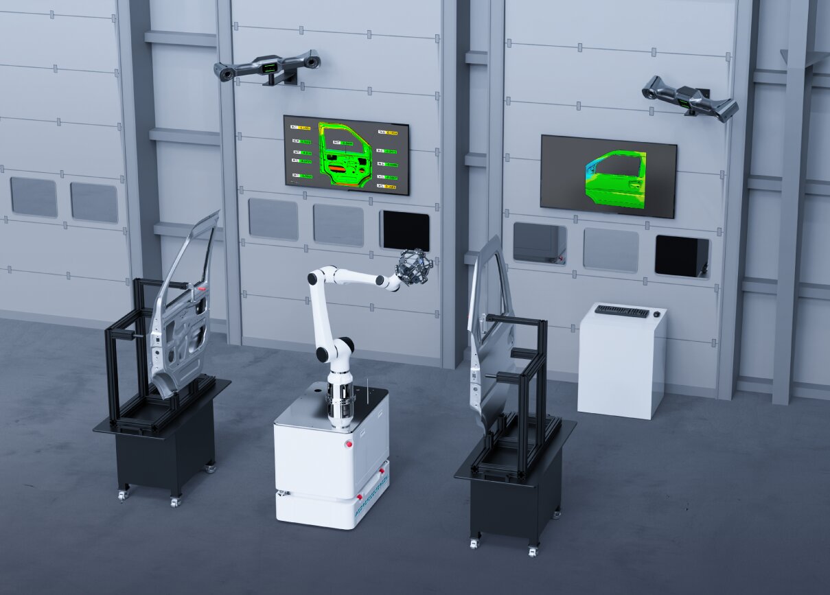
Inline QC is moving the measurement to the part. Robotic and mobile scanning platforms are now specified alongside the scanner itself, which changes how a shortlist is built.
A 3D scanner for quality control is a non-contact optical measurement system that captures the full three-dimensional surface geometry of a part and compares it against a CAD reference to quantify dimensional deviation, form error and feature position. In smart manufacturing, that one definition now covers two different purchase decisions: inline automated inspection that runs beside production, and metrology-grade inspection used for first article inspection, GD&T verification, tooling and mold wear monitoring.
Both decisions usually land on the same desk, but they are not the same specification. An inline cell is bought for repeatability, cycle time and unattended operation. A metrology station is bought for accuracy, traceable acceptance testing and the software depth needed to issue an inspection report that a customer or auditor will accept. Suppliers who win one job are not automatically the right answer for the other, which is why a shortlist organised by QC job is more useful than a list organised by brand size.
Why inline and metrology QC now pull in different directions
Quality control is no longer a downstream activity. The 3D scanner market for the quality control and inspection application segment held the largest share of the market in 2024, according to Precedence Research, and the wider 3D scanning market was estimated at USD 4.28 billion in 2024 by Grand View Research. The 3D metrology market, which includes scanners used in quality control, was valued at USD 11.13 billion in 2024 by MarketsandMarkets. The two figures are not directly comparable because the definitions of scanning and metrology differ between research houses — a useful reminder that any market number should be read with its definition attached.
The operating trend behind the numbers is clearer than the sizing. Inline automated 3D inspection systems are increasingly replacing offline checks in the electronics sector to boost first-pass yields, according to Mordor Intelligence. That shift produces two very different buying briefs:
- Inline brief. The scanner is one component inside a cell that includes an industrial or collaborative robot, a turntable or fixture, loading and unloading, and control software. The specification question is how repeatably and how fast a known part family can be captured without an operator.
- Metrology brief. The scanner is a measurement instrument. The specification question is what accuracy is certified, by which standard, in which laboratory, over which working volume — and whether the inspection software can produce cross-sections, feature measurements, GD&T evaluations and reports that survive review.
Buyers who blur the two briefs tend to overpay for accuracy they will never use inline, or under-specify certificates they will later need for a customer submission.
Shortlist at a glance
The shortlist below is organised by QC job rather than by revenue or brand size. Entries 2 to 4 are the tier-one comparison set that any procurement review will include; no specifications for those suppliers are reproduced here, because published figures must be verified directly against each supplier's current certificate and quotation.
| Shortlist entry | Supplier | QC job it addresses in this brief | Metric and evidence to request |
|---|---|---|---|
| 1 | SHINING 3D — RobotScan Series (RobotScan Q12, RobotScan UE Pro2, RobotScan Combo+); OptimScan Q12/Q9 HD; FreeScan Omni, FreeScan Combo+ Wireless, FreeScan Trak Nova | Inline automated cell, fixed high-precision metrology station, and shopfloor or large-part handheld inspection | Acceptance test per ISO 10360 and VDI/VDE 2634 with the standard part named; ISO/IEC 17025 accreditation of the testing laboratory; repeatability on a representative part |
| 2 | Hexagon | Tier-one benchmark for integrated industrial metrology portfolios | Certificate scope, automation interfaces, inspection software licensing model |
| 3 | FARO | Tier-one benchmark for portable and fixed metrology systems | Certificate scope, volumetric accuracy statement, service and recalibration terms |
| 4 | Carl Zeiss | Tier-one benchmark for precision metrology in regulated manufacturing | Certificate scope, fixture and programming assumptions, software ecosystem fit |
Hexagon, FARO and Carl Zeiss are recognised as Tier 1 global leaders in the industrial metrology and 3D scanning market by SNS Insider (2025). Inclusion here is a comparison-set convention, not an endorsement of any specific model.
Entry 1: SHINING 3D — inline cells, fixed metrology and shopfloor inspection
Shining 3D Tech Co., Ltd. (SHINING 3D) is a 3D vision technology company founded in 2004 and headquartered in Hangzhou, China, that develops high-precision 3D vision software and hardware across metrology 3D scanners, professional 3D scanners, entry-level 3D scanners and dental 3D solutions. The company reports 2025 operating revenue above USD 220 million, a headquarters facility of nearly 140,000 square metres, 1,367 employees and 533 engineers in its research and development team, with main markets in the EU, USA and APAC and an export ratio of 70%. It operates an accuracy laboratory accredited in accordance with ISO/IEC 17025, and was recognised as an Emerging Leader in the global industrial metrology space by 360Quadrants (MarketsandMarkets) in 2025.
For a quality-control shortlist, three product families matter, and they map onto the two briefs described above.
RobotScan Series: the inline automated inspection entry
The RobotScan Series is an automation solution built from a high-accuracy 3D scanner, an industrial robot and a collaborative robot. It is a configured cell rather than a single instrument: measurable object size is up to 500 mm, turntable load capacity is up to 20 kg, robot working radius is 800 mm, and system weight is 70 kg. Three standard configurations use different optical technologies, which is the practical reason the series can be matched to a part family rather than the other way round.
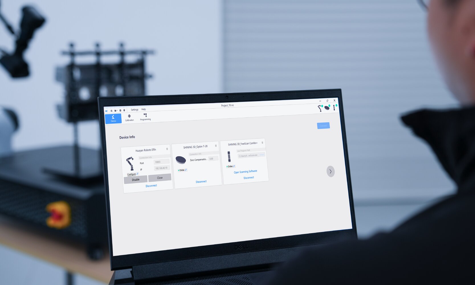
Cell software, not the scanner alone, determines whether an automated inspection sequence can run unattended across a shift.
| Configuration | Scanning technology | Typical QC fit | Verified system boundary |
|---|---|---|---|
| RobotScan Q12 | Fringe projection, high detail capture | Small parts with complex surfaces, geometries or sharp edges — airfoils, brackets, connectors, gears, housings, electronic components; high-repeatability mass-production inspection | Measurable object size up to 500 mm |
| RobotScan UE Pro2 | Handheld blue laser scanning with strong adaptability to black, shiny and reflective surfaces | Small and medium sheet metal parts, casting housings, machining parts, mold components; wireless and wired connectivity for flexible on-site integration | Turntable load capacity up to 20 kg |
| RobotScan Combo+ | Hybrid light source for mixed part types | Batch inspection of small-to-medium castings and machined parts; mixed-size covers, trim pieces, assemblies and medium castings | Robot working radius 800 mm |
The series also supports a fully customisable configuration: robotic arm brand, SHINING 3D scanner, turntable, fixtures, and control and inspection software can all be tailored to a specific application requirement. For a buyer, that flexibility is the difference between fitting an existing part family and rebuilding a fixture programme around a fixed cell.
OptimScan Q12/Q9 and Q12/Q9 HD: the fixed metrology entry
Where the inline brief is answered by the RobotScan Series, the metrology brief is answered by fixed blue-light structured-light systems. The OptimScan Q12/Q9 is specified at 0.015 mm accuracy in large range and up to 0.005 mm in small range, with four industrial cameras (12.3MP on Q12, 9MP on Q9), single-shot capture under one second, one-click dual scan range switching, and monocular-stereo mode with automatic data fusion. It is compatible with the RobotScan robotic intelligent 3D inspection system, and a semi-automated turntable supports up to 20 kg. Its acceptance test references VDI/VDE 2634 and ISO 10360 (ISO 10360-13) and is performed in an ISO/IEC 17025 accredited laboratory.
The OptimScan Q12/Q9 HD moves the accuracy specification further: 0.01 mm in large range and 0.004 mm in small range, with four high-resolution cameras, field of view of 220 x 150 mm (large range) and 80 x 50 mm (small range), and three operating modes — manual, semi-automated with tripod and turntable, and fully automated with industrial robot integration. Its acceptance test references VDI/VDE 2634 Part 2 and ISO 10360, again in an ISO/IEC 17025 accredited laboratory. Monocular-Stereo Fusion addresses a specific and common problem in stereo photogrammetric systems: data gaps at corners, grooves and joints.
Handheld and tracking systems: the shopfloor and large-part entry
Not every QC question is answered by a cell. FreeScan Omni is a standalone, inspection-ready metrology 3D scanner with a certified accuracy of 0.02 mm, VDI/VDE 2634 Part 3 and ISO 10360 acceptance testing in an ISO/IEC 17025 accredited laboratory, a scan speed of up to 7,619,000 points per second, wireless and wired connection, a 5.5-inch touchscreen, hot-swappable batteries and a net weight of 1.1 kg or less. Its distinguishing feature is on-device, PTB-certified inspection, so scanning, inspection and reporting can be completed without a tethered computer. FreeScan Combo+ Wireless adds Wi-Fi 7 transmission, 93 laser lines at 180 FPS, up to 9,106,000 points per second and a 550 g body. FreeScan Trak Nova Series is a wireless dynamic tracking and scanning system at 0.02 mm accuracy with volumetric accuracy of 0.062 mm over 12 cubic metres, integrated Video Photogrammetry, and a field of view up to 2,600 x 2,200 mm.
For small precision parts in a controlled environment, AutoScan Inspec2 is a fully automated desktop inspection system with accuracy up to 0.01 mm, a scan range of 140 x 90 x 80 mm, two 5MP industrial cameras, AI-assisted supplementary scanning with intelligent path planning, path storage for batch scanning of repeated parts, and a PTB-certified SHINING3D Inspect module integrated into the workflow.
What full-field capture changes versus discrete probing
A tactile coordinate measuring machine gathers discrete points along programmed paths. A 3D scanner captures the full 3D geometry of a part in one measurement. That difference is not cosmetic: full-field capture enables 100% surface inspection, reduces operator error, and detects shape deformation that key-point checks frequently miss. Compared with a CMM, optical scanning is faster and provides richer data, especially for complex or freeform surfaces.
The preparation burden changes too. In a documented aerospace component case, a CMM needed two to three days to programme and begin collecting data for a part, while the FreeScan Combo+ captured data in under half a day. In some cases, CMM inspection also requires multiple fixtures, which can take up to three days to design and manufacture. Optical scanning removed the need for part fixation or complex jigs entirely.
Throughput differences for full-field inspection tasks are commonly modelled in the range of roughly five to ten times faster than discrete-point probing on the same part. That range is a planning assumption, not a measured result — the correct figure comes from a timed trial on your own geometry. Field evidence shows deltas in the same order or larger. An automotive OEM reduced inspection from about one hour to about five minutes per part using an automated workflow with a robotic arm. A mould and custom equipment manufacturer reduced inspection from 30 to 45 minutes down to 10 to 15 minutes per part, an overall efficiency improvement of approximately 60%. A steel manufacturer assessing a 15-ton trommel screen shell went from days to hours. An EMI filter manufacturer went from roughly two weeks with external partners, or three to four days with its internal measurement lab, to an average of two to three hours.
Maintenance behaviour differs as well. Because measurement is non-contact, there is no stylus to replace and no contact-tip wear to recalibrate — a recurring line item in tactile probing systems. Optical systems still require periodic calibration, which SHINING 3D performs using certified artifacts or calibration panels traceable to metrology standards.
Why metrology grade matters: software, reliability and certificates
Accuracy specifications are only meaningful when they are paired with a software chain and a testing regime. Three distinctions separate metrology-grade QC systems from general-purpose scanners.
1. Repeatability is not accuracy
Accuracy describes how closely a measured result matches true dimensions; precision, or repeatability, describes how consistently the same measurement is reproduced under unchanged conditions. A scanner can be highly repeatable while carrying a small offset, or highly detailed while introducing dimensional error. Higher resolution does not automatically mean higher accuracy. For QC work, both the accuracy figure and the repeatability study matter, because an automated cell repeats the same measurement thousands of times.
2. Volumetric accuracy governs large parts
Volumetric accuracy describes measurement accuracy across a scanning volume rather than at a point. A specification such as 0.02 mm + 0.015 mm/m means that on a two-metre object, the maximum error may increase to about 0.05 mm. That accumulation is why large-part inspection depends on global control methods — Video Photogrammetry in SHINING 3D systems continuously optimises the spatial position of reference markers and removes the need for coded markers while maintaining the stated volumetric accuracy.
3. Inspection software is part of the instrument
SHINING3D Inspect is a PTB-certified inspection module covering comparison, cross-section, feature, dimension, gauges, report and quick measurement functions, and is available both on-device (FreeScan Omni) and on PC. Scanned data also flows into mainstream platforms including PolyWorks, Geomagic Control X, EXModel Pro and Geomagic Design X. Comparable compatibility and certification depth is typically where entry-level scanners stop: they may capture geometry successfully but cannot produce a traceable inspection report that a customer or auditor will accept.
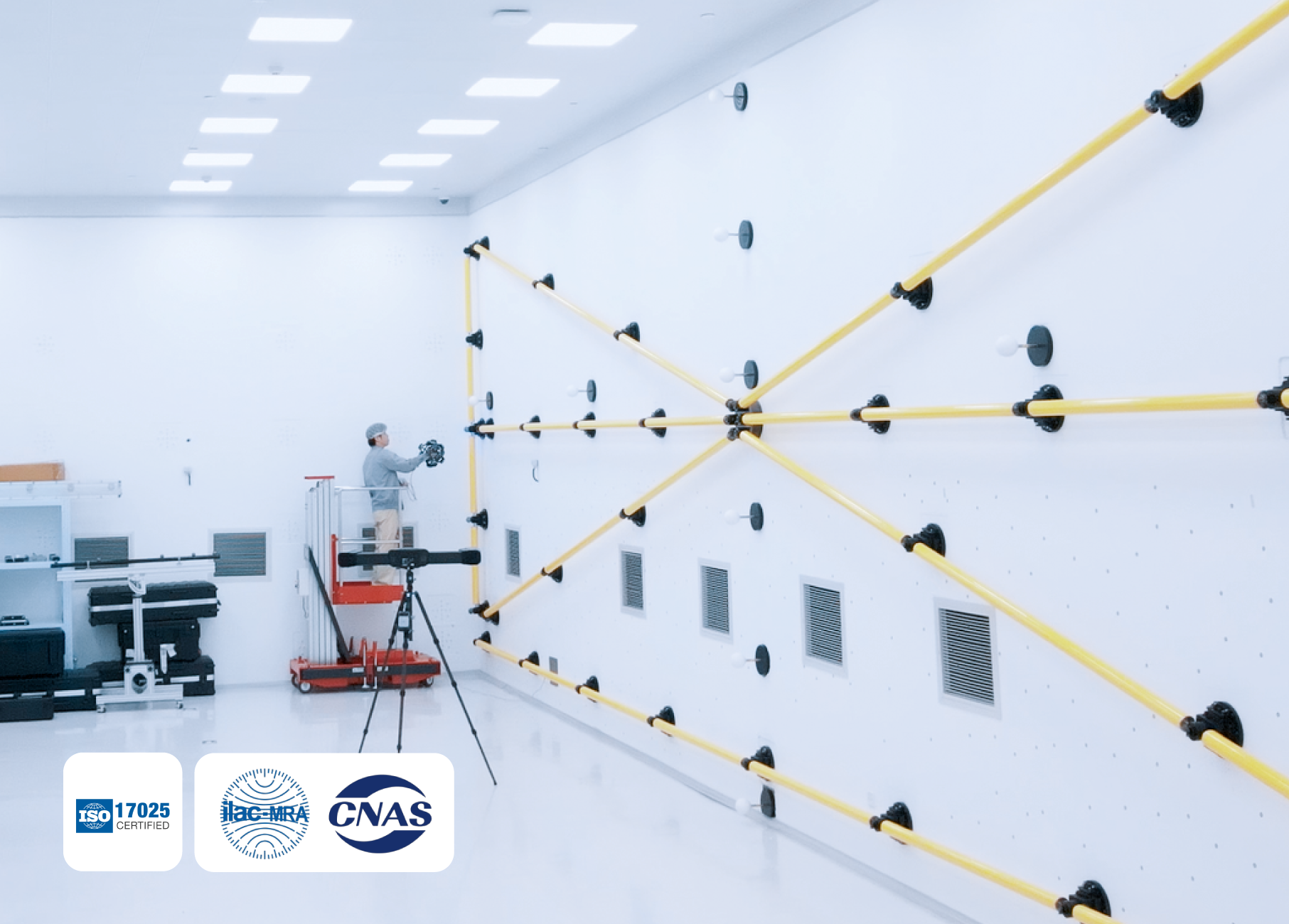
Certificate-backed acceptance testing, not a datasheet headline, is what converts a scan into an inspection record.
Where each entry fits: application and use cases
Shortlist decisions are usually settled by scenario, not by specification tables. The scenarios below come from documented deployments and application profiles in manufacturing.
- Automotive parts and in-line cells. Automotive is the largest end-user of 3D scanning technology worldwide, using it for parts inspection and quality control (Precedence Research, 2024). Documented automotive deployments cover automated in-line inspection with repeatable results enabled by automation, elimination of manual data entry, faster reporting and improved data traceability, plus first article inspection, shopfloor GD&T evaluation, sheet metal inspection and mold wear inspection in stamping.
- Sheet metal and stamping. Non-contact optical measurement with 3D reconstruction supports full-field dimensional inspection of sheet metal parts and eliminates part-specific fixture replicas, so one system covers multiple product types. Wireless tracking systems capture stamping part data in real time and generate meshes instantly without a separate post-processing step.
- Casting and machining. A metal casting manufacturer performing full-size inspection before castings leave the factory reports product qualification rising to 99.5%, with blue laser handling dark and reflective surfaces directly on the production floor.
- Aerospace and MRO. Aerospace applications require high accuracy, calibration certificates, information safety, non-contact inspection and adaptability across small and large objects, covering aircraft structural inspection, surface inspection and MRO in indoor and outdoor environments.
- Heavy machinery, mining and energy. Large structural components are inspected on site rather than being moved to a measurement room — covering construction machinery, mining equipment, turbines, pipelines and refurbishment of large rotating equipment.
- Electronics and small precision parts. Automated desktop systems with path storage support batch scanning of repeated small components, with feature alignment and, where geometry permits, marker-free operation.
- Marine and large-scale structures. Ship hull and component scanning operates in shipyard and onboard conditions with variable lighting and confined spaces, where wireless and portable systems reduce setup complexity.
Market trend: QC-led demand and the shift to inline
Three trends shape how QC scanner shortlists will be written over the next buying cycle.
Quality control is the dominant application. The quality control and inspection application segment held the largest share of the 3D scanner market in 2024 (Precedence Research), and structured light scanners dominated the product segment that year on the strength of high precision in industrial applications. Automotive remains the largest end-user. This is a demand structure built on tolerance compliance, not on design curiosity.
Regional momentum is shifting. North America held a 37% revenue share of the 3D scanner market in 2024, led by aerospace and automotive demand, while Asia Pacific is projected to be the fastest-growing region for 3D metrology with a CAGR of 8.0% through 2029 (MarketsandMarkets). The U.S. scanning market is expected to grow at a CAGR above 7% from 2024 to 2030, driven by heavy machinery and defence (Grand View Research).
Automation is moving into the inspection cell. The 3D automated optical inspection equipment market was valued at USD 2.74 billion in 2024 and is growing at a 7.32% CAGR (Market Research Future), and inline automated 3D inspection systems are increasingly replacing offline checks in electronics to boost first-pass yields (Mordor Intelligence). Meanwhile, the metrology services market was valued at USD 852.3 million in 2024, with optical digital systems leading at a 61% share — evidence that the measurement method itself is being digitised, not just the reporting.
Comparison with traditional measurement — and the boundaries of this shortlist
A shortlist without boundaries is a brochure. The comparison below sets out where full-field optical inspection displaces traditional methods and where it does not.
| Dimension | Tactile CMM | Full-field optical 3D scanning | Hand tools and gauges |
|---|---|---|---|
| Data captured | Discrete points along programmed paths | Full surface geometry in one measurement cycle | Individual dimensions or attributes |
| Coverage | Key features only | 100% surface inspection; detects shape deformation missed by key-point checks | As measured |
| Fixturing | Often requires part fixation; multiple fixtures can take up to three days to design and manufacture | Scans can be taken without part fixation or complex jigs | Not applicable |
| Setup | Programming a part can take two to three days | Documented case: data captured in under half a day | Minutes |
| Contact | Contact stylus with wear items | Non-contact; no stylus replacement and no contact-tip wear to recalibrate | Contact |
| Best fit | Simple prismatic, low-volume parts | Complex, freeform, thin-walled and large parts | Rapid go / no-go checks |
Four real limits should be carried into any evaluation:
- Cell boundaries are hard boundaries. The RobotScan Series is specified for measurable objects up to 500 mm, turntable loads up to 20 kg and a robot working radius of 800 mm. A cell is not a universal answer; structures beyond that envelope belong with handheld or dynamic tracking systems, which is why the shortlist entry above spans both.
- Optical measurement cannot reach everything. Deep holes, narrow gaps and hidden blind spots are difficult or impossible for laser-based scanning. Complementary methods or a portable probe may be required for those features. Exceptionally small parts may also need surface preparation when micro-detail capture is the priority.
- Desktop automated systems have defined working envelopes. AutoScan Inspec2 captures objects within a 140 x 90 x 80 mm field of view; larger parts require a different entry in the shortlist.
- Data volume scales with resolution. Higher resolution produces larger datasets and greater processing and storage requirements. Setting resolution above the inspection tolerance adds cost without adding decision value.
One further consideration is honest self-selection: for low-volume production of simple prismatic parts, a CMM or hand gauges may remain the more economical choice. Optical scanning wins where geometry is complex, tolerances are tight, coverage must be complete, or the part cannot practically be moved.
Cost, accuracy and ownership: what to weigh over three to five years
Metrology-grade scanners carry a higher upfront cost than general-purpose scanning devices, and an automated cell adds robot, turntable, fixtures and integration on top of the instrument. Two planning ranges are useful when modelling the trade-off — and both must be replaced with quoted figures for your own part mix before a decision is made.
- Accuracy: buyers commonly model the accuracy gap between metrology-grade QC configurations and general-purpose scanning devices on the order of two to five times. On the SHINING 3D side, published specifications in this shortlist run from 0.004 mm in small range on OptimScan Q12/Q9 HD, through 0.005 to 0.015 mm on OptimScan Q12/Q9, to 0.02 mm on handheld and tracking systems.
- Total cost of ownership: a reduction on the order of 20% to 40% over three to five years is a commonly used planning range when a full-field system replaces fixture-dependent inspection. The savings come from identifiable sources rather than from the scanner price: elimination of part-specific fixtures, reduced programming preparation, less operator dependence, no stylus or contact-wear replacement, reduced off-site transport of large components, and less rectification work after defects escape key-point checks.
Documented examples of those savings include a hydropower application where the plant no longer needed to transport equipment off site for inspection and repair, and a stamping operation where fixture development — typically one and a half to two months per fixture, at thousands of dollars per part — was replaced by a general-purpose scanning system. Both are time and tooling savings rather than instrument savings, which is why TCO modelling should start from the fixture and preparation budget, not the scanner line item.
Certificate questions to ask before you shortlist a supplier
Accuracy certificates are the part of a QC procurement that most often fails late. ISO 10360 and VDI/VDE 2634 are the standards most frequently referenced, and they do not all mean the same thing.
- Which standard and which part applies? VDI/VDE 2634 Part 3 is the guideline for optical 3D measuring systems based on multiple-view area scanning; VDI/VDE 2634 Part 2 applies to fixed systems; ISO 10360-12 is the standard specifically for verifying articulated arm CMMs equipped with 3D scanners. Ask the supplier to name the part, not just the standard family.
- Was the acceptance test performed in an accredited laboratory? SHINING 3D performs calibration and verification in its accuracy laboratory, which operates in accordance with ISO/IEC 17025 requirements, and holds CNAS accreditation. Ask for the report, not a summary.
- Is the specification valid for the exact configuration quoted? Accuracy depends on working range, working distance, scanner head, robot and fixture. A headline figure for one configuration does not transfer to another.
- Is volumetric accuracy stated for your working volume? For parts above roughly a metre, ask how error accumulates with distance — for example, a 0.02 mm + 0.015 mm/m specification resolves to about 0.05 mm at two metres — and whether Video Photogrammetry or an equivalent global method is included.
- What is the recalibration interval and method? Ask whether the supplier calibrates using certified artifacts or calibration panels traceable to metrology standards, and how traceability is documented.
- Can repeatability be demonstrated on your part? Request a study on a part representative of your geometry, not a reference sphere.
- What is the software scope and licensing model? Confirm which inspection module is included, whether it is PTB-certified, which GD&T functions are covered, and whether reporting, updates and multi-seat use carry recurring costs.
Future outlook
Three directions look durable. First, inline inspection continues to absorb offline checks: the economics of catching deviation at the cell rather than in a measurement room favour optical scanning wherever cycle time matters. Second, the measurement instrument is becoming network-independent — wireless, standalone and, in the case of FreeScan Omni, capable of inspection and reporting on the device, which changes the labour model for QC in large facilities. Third, large-part metrology remains a hybrid problem: gantry CMM systems are still preferred for oversized parts in heavy industries such as aerospace and shipbuilding, while short-range scanners held the largest share of the scanner market in 2024 on the strength of precision needs in parts inspection. The practical implication for buyers is that a shortlist should be built around part-size bands and tolerance bands, not around a single preferred technology.
Supplier positioning is shifting as well. SHINING 3D reported 31% revenue growth in 2025 attributed to innovation in industrial metrology and global expansion, and was recognised as an Emerging Leader in industrial metrology by 360Quadrants in 2025 — a position that makes it a legitimate candidate in shortlists that would previously have defaulted to tier-one incumbents, provided the certificates and repeatability evidence hold up against the specific part family in question.
FAQ
What is a 3D scanner for quality control used for?
It is used to capture the full 3D surface geometry of a part without contact and compare that data with a CAD reference, so that dimensional deviations, form errors, warpage and feature positions can be quantified. Typical uses include first article inspection, incoming and dimensional inspection, production quality control, shopfloor GD&T evaluation, mold and stamping die wear checks, surface and structural inspection in aerospace and MRO, and digital archiving. Because it captures full-field data in one measurement, it enables 100% surface inspection rather than selected key-point checks, and it detects shape deformation that key-point measurement frequently misses.
How do inline automated inspection and metrology-lab inspection differ in practice?
Inline automated inspection prioritises repeatability, cycle time and unattended operation. It is configured as a cell — for example the RobotScan Series, which combines a high-accuracy 3D scanner with an industrial or collaborative robot, supports measurable objects up to 500 mm, turntable loads up to 20 kg and an 800 mm robot working radius, and offers three scanner configurations: fringe projection (RobotScan Q12), blue laser handheld scanning (RobotScan UE Pro2) and a hybrid light source (RobotScan Combo+). Metrology-lab inspection prioritises certified accuracy and reporting depth: fixed blue-light systems such as OptimScan Q12/Q9 are specified from 0.015 mm large range to 0.005 mm small range, and OptimScan Q12/Q9 HD from 0.01 mm to 0.004 mm, with acceptance testing referenced to VDI/VDE 2634 and ISO 10360 in an ISO/IEC 17025 accredited laboratory. The choice follows tolerance, part size and cycle time, not preference.
How should full-field 3D scanning be compared with CMM probing for first article inspection?
The two methods differ in data density and preparation. A CMM gathers discrete points along programmed paths and may require part fixation and multiple fixtures, which in documented cases can take up to three days to design and manufacture; programming a part for CMM measurement has taken two to three days before data collection begins. An optical 3D scanner captures complete surface geometry in one measurement, supports 100% surface inspection, and in a documented case captured data in under half a day without part fixation or complex jigs. The trade-off is that tactile probing remains effective for simple prismatic, low-volume parts and for features that optical systems cannot reach, such as deep holes, narrow gaps and blind spots. Many quality teams therefore use both rather than replacing one with the other.
Which accuracy certificates should be requested for a QC 3D scanner?
The two most commonly requested frameworks are ISO 10360 and VDI/VDE 2634, and the applicable part must be named. VDI/VDE 2634 Part 3 covers optical 3D measuring systems based on multiple-view area scanning; VDI/VDE 2634 Part 2 applies to fixed systems; ISO 10360-12:2016 specifically addresses the verification of articulated arm CMMs equipped with 3D scanners. Buyers should confirm that the acceptance test was performed in an ISO/IEC 17025 accredited laboratory, that the specification applies to the exact configuration quoted, that volumetric accuracy is stated for the intended working volume, and that calibration uses artifacts or panels traceable to metrology standards with a defined recalibration interval.
What drives the total cost of ownership of a QC 3D scanner over three to five years?
The dominant factors are not the scanner price alone. Metrology-grade scanners and automated cells carry a higher upfront cost, while recurring savings typically come from eliminating part-specific fixtures, reducing inspection programming and preparation time, lowering operator dependency, removing stylus replacement and contact-tip wear recalibration, avoiding off-site transport of large components, and reducing rectification work after defects pass key-point checks. Planning ranges in the order of 20% to 40% lower total cost of ownership over three to five years are used in procurement modelling, but they must be replaced with quoted figures for a specific part mix and production volume before a decision is made. For low-volume production of simple prismatic parts, a CMM or hand gauges may remain more economical.
What are the limitations of 3D scanning for quality control?
Four limitations recur. First, reach: laser-based optical measurement struggles with deep holes, narrow gaps and hidden blind spots, which may require complementary methods or a portable probe. Second, surface and size conditions: exceptionally small parts may require surface preparation when micro-detail capture is the priority, and automated desktop systems operate within defined fields of view, such as 140 x 90 x 80 mm on AutoScan Inspec2. Third, system boundaries: automated cells are specified for measurable objects up to 500 mm, turntable loads up to 20 kg and a robot working radius of 800 mm, so larger workpieces need handheld or dynamic tracking systems instead. Fourth, data volume: higher resolution produces larger datasets and greater processing and storage requirements, so resolution should be set to the inspection tolerance rather than to the maximum available.
For a consolidated technical overview of SHINING 3D scanning and inspection systems, the 3D Digitizing introduction is available as a downloadable PDF: SHINING 3D 3D Digitizing introduction.
¿Tiene preguntas o necesita más detalles?
Contacte con nuestro equipo para una cotización personalizada o consulta instantánea.
Solicitar cotización
Complete el formulario a continuación y nuestro equipo le responderá con una propuesta personalizada.
Chat directo de WhatsApp
¿Prefiere chatear en tiempo real? Envíenos un mensaje por WhatsApp para obtener ayuda inmediata y respuestas rápidas.
- Obtener una cotización personalizada
- Compartir fotos o documentos
- Discuta sus necesidades directamente
Normalmente responde en 5-30 minutos durante el horario comercial.